Saturday, November 19, 2011

Roxanne's Videos, addendum

In response to my last post, Roxanne graciously posted a new video honoring the Rox Box puzzle box I made for her last year, and which I discussed in an earlier post.

Just to clear up a little confusion, I engraved the gemstones but I didn't actually build them.  These were lab-grown gemstones, technically real rubies and sapphires but not natural rubies and sapphires.  Gem Select has a nice, balanced explanation of synthetic gem stones here if you're curious.  It's informative and respectful, but they don't trade in synthetic gems so they aren't pushing a product.

The clear plastic 'windows' in the Rox Box were literally 3D printed already-assembled by building the majority of the puzzle using white material, then switching to transparent material for the last few millimeters.  This is how the model looked when it came out of the printer, embedded in a solid block of white material with a few layers of clear material (at right).

After I cleared the material from the inside of the models I could see through the windows, but the parts were still embedded in unused support material from the build process.

Peeling away the material around the exteriors revealed the finsihed Rox Box parts, complete with their transparent windows for the top and bottom.  This is how the puzzle box looked the first time I got to see it!

Thursday, November 17, 2011

Roxanne's puzzle videos

Roxanne Wong is an extraordinary puzzle collector whose YouTube channel is crowded with reviews of puzzles by various ambitious designers throughout the world. A few are puzzles I've previously discussed or worked on.

George Bell's Dice Box
I built these hinged parts to George Bell's specifications, as described in an earlier blog post.

George Bell's Exploding Ball
George allowed me build my own Exploding Ball last year. In this video Roxanne exhibits a colorful version of it.

Air, by George Hart
This puzzle inspired my Rhombic Dodecahedron puzzle.  George Hart's web page shows examples of the pieces assembled and unassembled.

Cuburr
Cuburr is uniquely optimized for the SD300 build process, as described in an earlier post.

Tuesday, November 8, 2011

Helical Burr Experiment

After seeing my Rhombic Dodecahedron Puzzle Bram Cohen casually suggested a puzzle in which one particular piece has to be put in last.  That is to say, a puzzle in which the pieces must be assembled in a particular sequence.

The picture above shows how the idea might be adapted to one of my swirly 'marble' puzzles: the four pieces must be assembled in the sequence illustrated above because each new piece blocks the movements of the previously installed pieces.

Anxious to try it out, I built a set of pieces without checking their dimensions.  But I encountered some delicate, thin walls while I was peeling the models out of the support material.

 VisCAM revealed some astonishingly thin, wispy structures on the thinnest piece.  Some of the walls taper down to less than 0.1mm near some of the edges.  It held together only because the super-thin portions are anchored to the thicker 'backbone' up the center!
It took a lot of slow, cautious work to free this thin part from the leftover plastic but it came out intact!  Dipping the piece in plastic-welding solvent made it strong enough for functional testing, despite a few frayed-looking edges where the walls taper down to nothing.


Reviewing the measurements it became clear that the super-thin walls had occurred as a result of how two spiral-shaped channels gradually converged inside the puzzle.  Luckily the thin piece would be amply protected by the thicker piece when the puzzle is assembled.
As I'd hoped, the pieces can only be assembled in a specific sequence.  But unfortunately they fit together too tightly, so the last piece wouldn't go in.
I tried to improve the fit by sanding the pieces, but the PVC is just too soft for hand sanding so I resorted to a high-speeed abrasive wheel.  This improved the fit and gave the pieces a nice smooth feel.

Perhaps it's a bad habit to keep building models with such thin walls, as they're extremely vulnerable to breakage while cleaning the model.  But even though they could break during manual cleanup, they don't pose any sort of danger to the build process so the main penalty is the tedious labor.  The SD300 can safely attempt any sort of ridiculous geometry, even if the STL file is riddled with defects, and the worst that might happen is the model might be disintegrate or consume excessive labor during post-build cleaning.

Tuesday, November 1, 2011

Making signs with deeply-engraved letters

This amusing Do Not Disturb sign was adapted from a humorous sign in the animated TV series Moral Orel.  A Thingiverse user shared the design in several formats so it could be built using a laser cutter, robo cutter, or 3D printer.

I built it on the SD300 by starting with ivory/white material for most of the build and then substituting red material for the last layer.  That resulted in neat, sharply-defined letters in deep relief.

I liked the joke so I took it a step further, designing a door hanger and sharing it as a derivative design.  I flattened the design a little, but kept some depth because the relief makes the graphics look attractive.

Thursday, October 20, 2011

"Screwy" Screw

 A Thingiverse user saw my Wrong Way Nut video on YouTube, which showed two nuts traveling in opposite directions on the same screw thread.  He was inspired to create his own version of it, which he named Screwy Screw.  Full marks for that name!

It was interesting to see how he came up with a similar solution, yet made some vastly different aesthetic choices.  Most conspicuously, his Screwy Screw is much larger than my own bolt model.
Here's a quick video comparison of Screwy Screw against samples of Wrong Way Nut built on my SD300 and another sample built by Bradley Rigdon courtesy of http://printo3d.com/
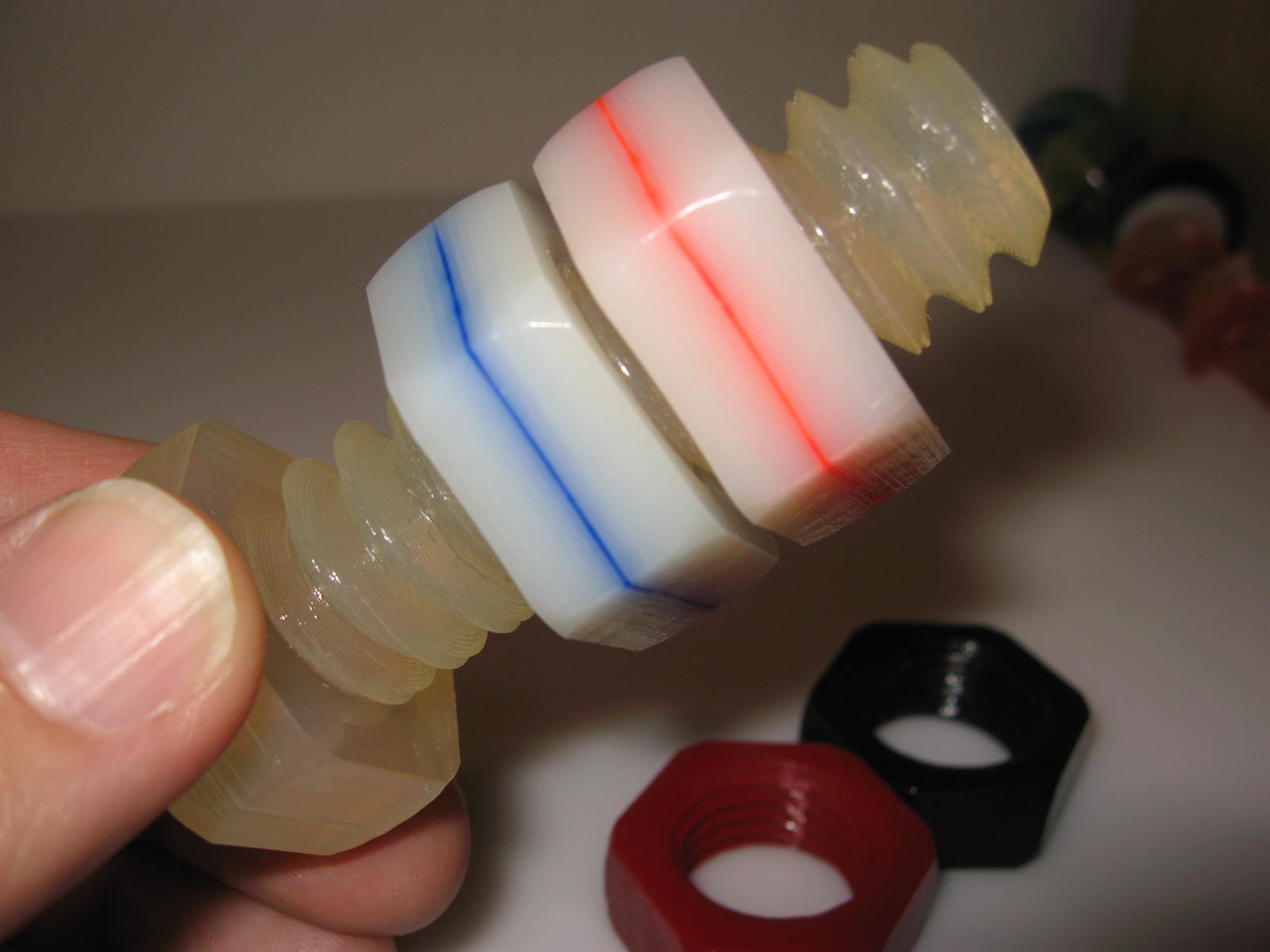
Here's a closeup of the FDM samples of Wrong Way Nut, built by Bradley Rigdon.  Notice the funny patterns on the side walls?  See below.

Below is a closeup comparison of a nut built on the SD300 (red) and one built on a Dimension by Stratasys (blue).  Both build processes produce these wave-like patterns, often referred to as "chatter", as a result of very subtle vibrations that occur as the machine changes direction at the corners.  The marks don't affect the model's tolerances--in fact they're hard to see except by examining the model's sheen under a bright light source as here.
STL files for Wrong Way Nut are downloadable from Thingiverse here.

Sunday, October 16, 2011

Gear O'Clock

Last week Bradley Rigdon shared Gear O'Clock, a novel clock that indicates the current time using a large geared ring with numbered tabs around its rim.  This week I posted a set of Accessory Parts to adapt or customize Gear O'Clock.

Bradley used a clock movement salvaged from an inexpensive wall clock he bought at Wal-Mart.  I set out to adapt the parts for use with an ArtMinds clock movement from my local Michaels craft store.

For the benefit of Thingiverse users, here's a detailed explanation of my accessory parts:


Clock Drive Gear slotted NO SUPPORT.stl has a slotted opening that fits over the threaded hour-hand shank on the craft-store clock movement.   It took some effort to avoid excessive overhangs so the part retains its buildability on hobby 3D printers.  I added a wide opening on the back side of the gear because some of the craft store movements have big shanks (like this one).


The slotted-shape of the shank keeps the Drive Gear synchronized with the shaft, just as a conventional hour hand would be.  The clock movement kit includes a threaded brass ring that screws over the Drive Gear to secure it in position.

Some of the clock movement kits have short shanks and others have really long shanks like the one illustrated here, so I added a small fence inside the deep gear teeth so the driven clock gear won't tend to walk out of the back side of the Drive Gear.

Bradley's Clock Base ring is 10 inches in diameter so it can't be built in one piece on the SD300, nor on most hobby 3D printers.

Clock Base div4.stl divides the Clock Base into four parts, which can be spliced using the number tabs at the 3, 6, 9, and 12 o'clock positions.
 The number tabs are keyed into holes in the Base Ring, so I glued one number tab to the end of each of the four parts.
 Then join each piece to the next by hooking it into the keyed holes and injecting glue between the surfaces.  Notice how the diagonal join ensures a gradual transition from one section to the next so the gear won't snag when it turns in the clock.  Be sure to attach the numbers counterclockwise relative to an ordinary clock!


My revised Drive Gear exposes a hole for the clock's second hand, so I designed Clock Seconds Gear.stl to cover the hole and add a little animation to the clock.

This gear has a hole and a slot in the back to accommodate the original second hand from the clock movement kit.  The original second had can be left intact or clipped off.

After the Clock Seconds Gear is attached to the second hand parts, it pushes into the exposed opening in the clock shank.

The craft-store clock movement has a built-in wall hook so it wouldn't fit in Bradley's enclosed Clock Mechanism Mount.  Clock Mechanism Mount cutout.stl adds a cutout to accommodate the movement's wall hook.


Some clock movement kits feature a moving pendulum, which adds even more animation to the clock.  So I built the even-larger Clock Mechanism Mount Pendulum.stl mount which has another cutout on the bottom for the pendulum mechanism.
Clock Gear Pendulum.stl is a gear-themed pendulum for use with the pendulum-type clock movement kit.


For further reference:
  • The original Gear O'Clock files are located at Thingiverse
  • My accesory files are located at Thingiverse here
  • Bradley's video shows how the clock should be assembled at YouTube
  • Here's a video showing my clocks with moving second hands and pendulum.
  • An online shop that offers all sorts of clock kits at http://www.klockit.com/

Thursday, October 13, 2011

Rhombic Dodecahedron Puzzle

I just shared a simple Rhombic Dodecahedron Puzzle at Thingiverse, consisting of four identical pieces that fit together to form a solid shape.  The concept is very similar to my previous marble puzzles and cubic trisections, but using four parts instead of just two or three.

The idea of using a shape with four-way symmetry was inspired by George Hart's Air puzzle, which is described on his web site and briefly demonstrated in a YouTube video by Roxanne Wong.

Like my previous dissection puzzles, the pieces have a distinct orientation so they only fit together if they're all pointed the same direction.  Technically that means my puzzle only one-eighth as many duplicate solutions as Air but that doesn't mean it's any harder to solve.

Here's a video that demonstrates how the puzzle works.

Tuesday, October 11, 2011

Power Interruption

Last weekend a brief blackout interrupted the SD300 while I was recording a video.  I kept recording and captured the SD300's recovery when the power came on again a minute later.  This video is embarrassingly awkward and rambling, but it's potentially interesting because most 3D printers can't recover as elegantly as the SD300 did in this video.  (More on that below.)


The SD300 is connected to a netbook running on batteries, so it recorded exactly what the SD300 was doing when the power went off.  The log says it was "Taking logical tool 4" which means it was picking up the 1mm Anti-Glue pen for masking fine details, whereupon it suddenly encountered a "WriteFile Error" because the SD300 had lost power and stopped responding.

When the power came on again, the log recorded how the computer re-established its connection with the SD300.  Because the SD300 remembered it had been building a model it calibrated the Z-axis to the top of the model instead of the top of the build table.

Recovering from a power failure isn't always so effortless as it was here, but it's usually quite manageable.
  • The computer didn't lose power.  If the computer had also lost power then it would have been necessary to reboot and start the SDView software again.  The computer saves a copy of the current model on the hard drive so it can recover and continue if the computer is turned off during a build.
  • The SD300 just happened to get interrupted between changing Anti-Glue pens.  As a safety measure the SD300 won't initialize until it detects all pens are parked in their storage holders.  If it had lost power while it was actually using a pen then it would have requested the user manually return the pen to the storage holder before it would re-initialize.
  • Additionally, if the SD300 is interrupted while the top layer of the model is still attached to the material roll then it would need to cut it free before it could initialize the Z-axis.  If that had occurred, the SD300 would have adjusted the table to a safe position, reset the XY axis, and requested permission from the user to "Trim layer?"

Wednesday, September 28, 2011

Triangular Dovetail Joint

Woodworkers have made trick dovetails for years, probably centuries.  I designed this trick joint because I hadn't seen any triangular dovetail joints.  Not surprisingly, it has been done before.

All three exterior sides show identical dovetail-like joints, which makes it look impossible to open.

But the pieces don't slide like a conventional dovetail.

The two pieces rotate until they gently let go of each other.

There's a hollow cavity inside, so it can be used as a puzzle box.  Not that anyone would be terribly puzzled--it looks odd, but it's easy for anyone to open once they pick it up.

This is a simple, traditional puzzle box so I've posted the STL files at Thingiverse for anyone who wants to play with it.

Tuesday, September 20, 2011

Spring-o-sphere


Schorhr's Spring-o-sphere model on Thingiverse looked like a perfect example of a model that's unsuitable for building on the SD300: very thin walls surrounding a large trapped volume.  But that made me curious, so I included the Spring-o-sphere in a batch of models back in June.

I anticipated there might be trouble peeling the support material away, so I put a box of peeling cuts around the Spring-o-sphere so it would be isolated in its own little 'brick.'


As expected, it was tedious peeling away all the enclosed material a tiny bit at a time.  Right at the start the little hook broke off the top, so I expected more breakage.

But the rest of the material peeled away without any further breakage.

The body of the spring proved to be surprisingly resilient.  On close examination I could see lots of little loose ends.  These are unsightly but they don't seem to weaken the spring.


Evidently this unexpected resiliency was imparted by the long overlap between layers.  There's exactly 1 layer of red material in the model, but red band shows how that layer extends a long distance around the spring, thereby giving it ample distance to be bonded with the layers above and below.


It's a nice container for holding shiny objects.


Despite my relative success building this Spring-o-sphere, I still regard it as a model that's basically unsuited to the SD300 build process.  But the experiment suggests I could choose to build such a model in a pinch, provided I'm willing to sacrifice the model's visual appearance (eg: broken hook, loose ends) and invest extra effort (eg: repair hook, tedious peeling).  I certainly wouldn't recommend doing this sort of model routinely, but it's nice to know I could.