Showing posts with label tools. Show all posts

Wednesday, February 6, 2013

Moiré Maze for laser cutter

I took last month's injection-molded prototype for Moiré Maze and adapted it back for laser cutting by projecting it into 2-dimensional layers and tracing their outlines.  I don't own a laser cutter, but plenty of businesses offer laser cutting services including mail-order Ponoko.  But why wait for the mail?

The SD300 can make good simulations of laser-cut parts, given adequate model data.  I created accurate simulations of laser-cut models by first modeling a sheet about the anticipated thickness of the part, about 3.0 mm to simulate the typical "eighth inch acrylic" (which usually runs a tad thin).  To simulate a laser's cutting behavior I cut the outlines using a "thin wall cut" with a 2 degree draft angle.

Models were easy to clean because the sheet-like design meant there weren't any overhangs, undercuts, or loose ends to deal with.  It was easy to stab leftover support material and peel it away from both sides of each finished piece.

I also designed a 2-piece base, shown upside-down here, on which the maze layers are stacked.  The base aligns the maze pieces and holds them together.

The magnetic wand can be stored in a compartment at the top edge of the maze, and it's held in place because the magnets in the wand are attracted to steel beads embedded inside the model.

Above is a brief video tour of Moiré Maze.

Moiré Maze was inspired by Boston Subway, Oskar van Deventer's design for IPP26 shown at left in the picture.  Boston Subway has layers of criss-crossing channels built from laser-cut acrylic, and the goal was to guide a little magnet from "work" to "home" using a magnetic wand.  Moiré Maze substitutes ring-shaped channels for the straight ones, and thereby creates a visual hiding place for its solution even though it's entirely transparent!

Friday, April 13, 2012

Fluctuating Build Economy

I've produced a ton of test models for my Cooksey's Griddle puzzle of the past month because I discovered how to build them cheaply with relative ease.  That's quite a change from my experience in February, when I had so much trouble building prototypes of it that I gave up and submitted the model to i.Materialise to build it for me--but they couldn't build it either.  (Bad STL file, I think.)

But I didn't really set out to build so many test models, it just happened.  The first model worked fine but someone suggested a nice improvement so I built another.  Then someone suggested another change, and I built another to try it out.  Eventually I built over a dozen test models, each with minor differences from the last.  There are so many that I'll discuss the details of the puzzle in another post.

In this post I'll concentrate on the surprising economy of this particular model...

Originally this puzzle was designed as a flat slab with a 16mm round disc attached.  Above, the diagram shows it with a rectangular outline around it showing the volume of material the SD300 would build to create this model.  Much of the area above and below the slab is just empty space, but the SD300 would consume that much material in order to support the slab while it built the disc.  This would consume less than $30 worth of material, much cheaper than sending it to a 3D printing service...even deep-discount Shapeways.

But material costs (and build time) were reduced by two-thirds if I built the disc as a separate piece to be glued onto the model after building it.  As shown above, no volume would be wasted above or below the slab.

I could realize a further savings by building two models at a time.  That gave me two complete puzzles in each build job, complete with all their accessories, for less than $10 per puzzle.  Each job consumed only 6% of an SD300 material kit; I could build 32 of these puzzles with 1 box of SD300 material.

Particularly critical was the use of a precision probe, like this Moody Tools set, to peel material out of the narrow grooves.  These probes are also excellent for clearing small holes without marring the model, especially in narrow or deep locations where the standard Solido-supplied tweezers aren't optimal.

Wednesday, March 7, 2012

Cooksey's Griddle

I finally managed to build my Cooksey-inspired flat maze on the SD300.  My last build failed because I'd been using a worn cutting knife, and this model packs a whole lot of cuts into a very tight space.  I put in a new, factory-calibrated knife shortly before building this model.


I'd used three colors by switching materials between the major areas of the puzzle.  That yielded a surprise bonus because unused material was consequently color-coded to easily distinguish the difficult middle section.


I had programmed SDView with an elaborate scheme of peeling cuts to ensure the middle layer could be cleared from the outside, but I'd still overlooked a design detail.  Consequently, a lot of the material had to be freed by tediously tugging pieces of material sideways before pulling it out through the openings.


When the puzzle is fully assembled, the shuttle rests in a grooved handle.  The side walls keep it securely nested in the handle.


A disc at the bottom of the handle prevents the shuttle from coming off at the end, so the only path to remove it is to slide the shuttle into (and through) the maze.


The tab on the shuttle only allows movement along one axis (vertical) when it travels on the red side.  Horizontal  movements are blocked so long as the tab rests on the red-side grooves.


Another tab can be pushed into the blue grooves on the flip side of the maze.


Engaging the tab on the blue side disengages the tab on the red side, so horizontal movement is no longer blocked.  This allows the shuttle to move left & right as far as the groove on the blue side permits.


The user navigates the maze by alternately engaging the tab in the blue side for horizontal movements and engaging the red side for vertical movements.  Neither side exhibits the actual maze, so the correct path is not apparent.


Eventually the shuttle emerges from an opening near the start of the puzzle.


The shuttle is still hooked over the puzzle's handle, but now the tabs aren't locked into the grooves in the handle.


This arrangement allows the shuttle to spin around on the handle so the tabs move to the other side.


Now the shuttle can re-enter the maze, but with the tabs on opposite sides from before.  Now the horizontal movements occur on the red side and vertical movements on the blue side.  It's a completely different maze, without any similarities to the first.


By navigating through the mazes as shown, the user can eventually remove the shuttle through an opening at the top of the puzzle.  Naturally it's not quite as simple as it seems because there's still a subtle subterfuge or two.

Wednesday, January 25, 2012

Peppermint Candy puzzle refined

I took another stab at the Peppermint Candy puzzle which had been vulnerable to coming apart in unintended ways.  I carefully refined the curves so each piece would 'reach around' to brace itself against the back side of the puzzle and made the walls thicker so it would be more rigid.

Honestly, I wasn't sure it would suffice.  But it worked!

Here's the side with the ball sticking out.  The cut in the ball is lined up with the cuts in the shell but it won't open in this position.

The other side of the puzzle looks about the same, but it has a white dome instead of an opening so the ball can't be seen from this side.  The parting line forms an S-shape where it passes through the domed part.

Here's a video explanation of the puzzle in detail.


For comparison I ordered a test part built in SLS nylon.  It's stiffer than the part built on the SD300, a good thing, but it lacks the contrasting colors.  But the colors aren't just cosmetic; my testers thought the colors contributed to the challenge of solving the puzzle.

I built the ball pieces in a very specific orientation in order to put the colors exactly where I wanted them.  Here's how the ball looks outside the puzzle shell.

Since the part required a specific build orientation I couldn't really position it for optimal post-processing.  Each piece had a thin edge that would have been particularly vulnerable to chipping during cleaning, so I isolated that area in a little 'box' of peeling cuts.

Most of the layers in the isolated box fell away when the surrounding areas were cleaned, so it didn't make the cleaning work any slower.  Except when I got to the thinnest part, the isolated box allowed me to gently peel away the last bits of material...leaving the thin edge smooth and intact.  As usual, I solvent-dipped the parts to give them greater strength and a slick finish!

Monday, January 9, 2012

Antichron

A year ago I probably wouldn't have attempted to build something as twisty and complex as Bathsheba's Antichron model.  But someone sent me a reduced-size model of it, and I confidently devised a small set of peeling cuts that should have made it an easy build on the SD300.  Not so easy, as it turned out.

I got it mostly right.  I'd divided the model into four zones in each of the upper and lower sections, so the support material peeled away effortlessly at first.

But when I got near the middle section I found layers of support material permanently wrapped around sculptural features I'd misinterpreted.  If it had been properly planned, there should have been additional cuts to divide the support material but I hadn't instructed the SDMove software to make the proper cuts.

Was it necessary to discard the model just because I hadn't set up the build software properly?  Probably not, but I decided to free the model so from the rest of the material to get a better view of the trouble spots.

The support material was thicker than the walls of the model so I couldn't just remove them by brute force.  So I decided to separate the support layers and snip them one-at-a-time with a small knife.  This was tedious but it would free the model after cutting through dozens of layers on each side.  That would take a while so I put on an old Edward G. Robinson movie (Scarlet Street) while I worked...and it took most of the movie to free the two models I'd built.

Because I'd scaled down the model by 50% the walls were dangerously thin, about 1.4mm.  Somehow I managed to free the first model without any damage, but cracks appeared in the second model while I was cleaning it so I stopped several times and applied Weld-On to strengthen its weak spots.  When I finished cleaning the second model (below right) I dipped it in Weld-On 2004 to heal the cracks and give it a nice sheen.

Tuesday, September 20, 2011

Spring-o-sphere


Schorhr's Spring-o-sphere model on Thingiverse looked like a perfect example of a model that's unsuitable for building on the SD300: very thin walls surrounding a large trapped volume.  But that made me curious, so I included the Spring-o-sphere in a batch of models back in June.

I anticipated there might be trouble peeling the support material away, so I put a box of peeling cuts around the Spring-o-sphere so it would be isolated in its own little 'brick.'


As expected, it was tedious peeling away all the enclosed material a tiny bit at a time.  Right at the start the little hook broke off the top, so I expected more breakage.

But the rest of the material peeled away without any further breakage.

The body of the spring proved to be surprisingly resilient.  On close examination I could see lots of little loose ends.  These are unsightly but they don't seem to weaken the spring.


Evidently this unexpected resiliency was imparted by the long overlap between layers.  There's exactly 1 layer of red material in the model, but red band shows how that layer extends a long distance around the spring, thereby giving it ample distance to be bonded with the layers above and below.


It's a nice container for holding shiny objects.


Despite my relative success building this Spring-o-sphere, I still regard it as a model that's basically unsuited to the SD300 build process.  But the experiment suggests I could choose to build such a model in a pinch, provided I'm willing to sacrifice the model's visual appearance (eg: broken hook, loose ends) and invest extra effort (eg: repair hook, tedious peeling).  I certainly wouldn't recommend doing this sort of model routinely, but it's nice to know I could.

Wednesday, August 31, 2011

A Peek into Peeling Cuts

I've received several questions about peeling cuts and removal of the extra material, so here's a brief peek at peeling cuts with my recent screw & nut projects.

The SD300 builds by ironing layers of PVC film on top of the build platform one-at-a-time, and selectively bonding and cutting each layer of PVC film. Regions that belong to the model are bonded to the layers above and below, and unused material is left in-place (as to act as support material) until the build is finished.

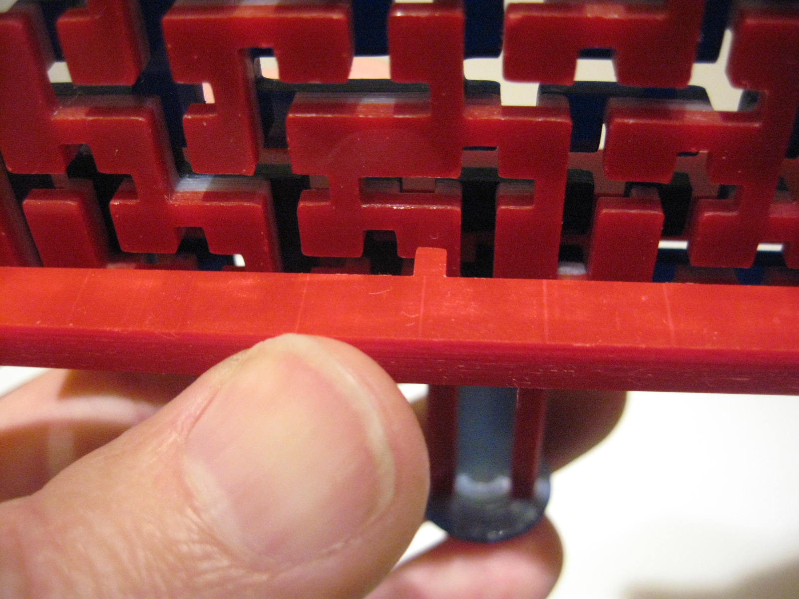
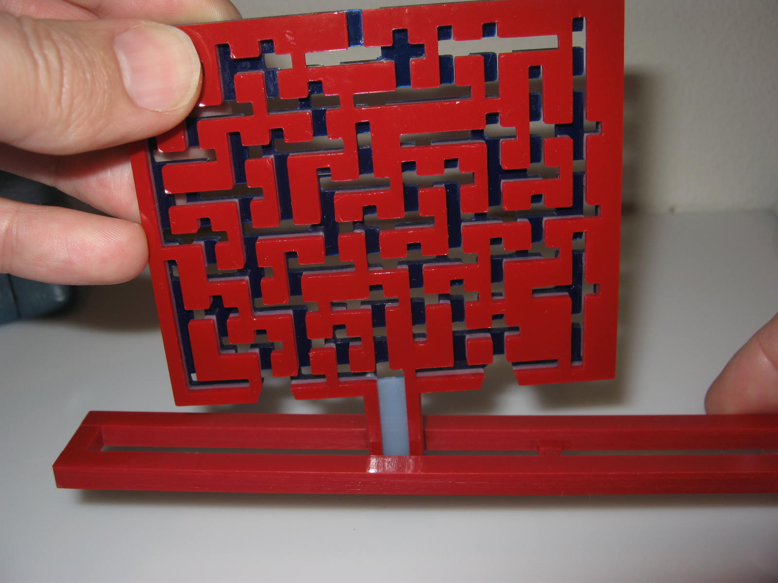
Before building these four bolt models (yellow) I added one long peeling cut (blue) to divide the unused material into two halves. The layers of PVC will be stacked parallel to the table, so the peeling cut is perpendicular to the actual layers of the model.


There's no single "right" way to arrange peeling cuts. You could add as many peeling cuts as you want so long as there are enough cuts to free the model from the surrounding material. Here I arbitrarily added an extra peeling cut to isolate some of the support material into two sub-regions.


Thanks to the extra cut, the material peeled away from two of the screws at a time instead of all four. It took longer than it might have, but there's no harm in making extra peeling cuts. Peeling cuts only affect the unused material, they don't cut into the model itself.


The nuts were a little more complicated. I don't put small cuts inside hollow models like I used to because I've learned a better way to remove the material inside holes. (I'll explain that below.) I added peeling cuts between adjacent nuts, but not inside.


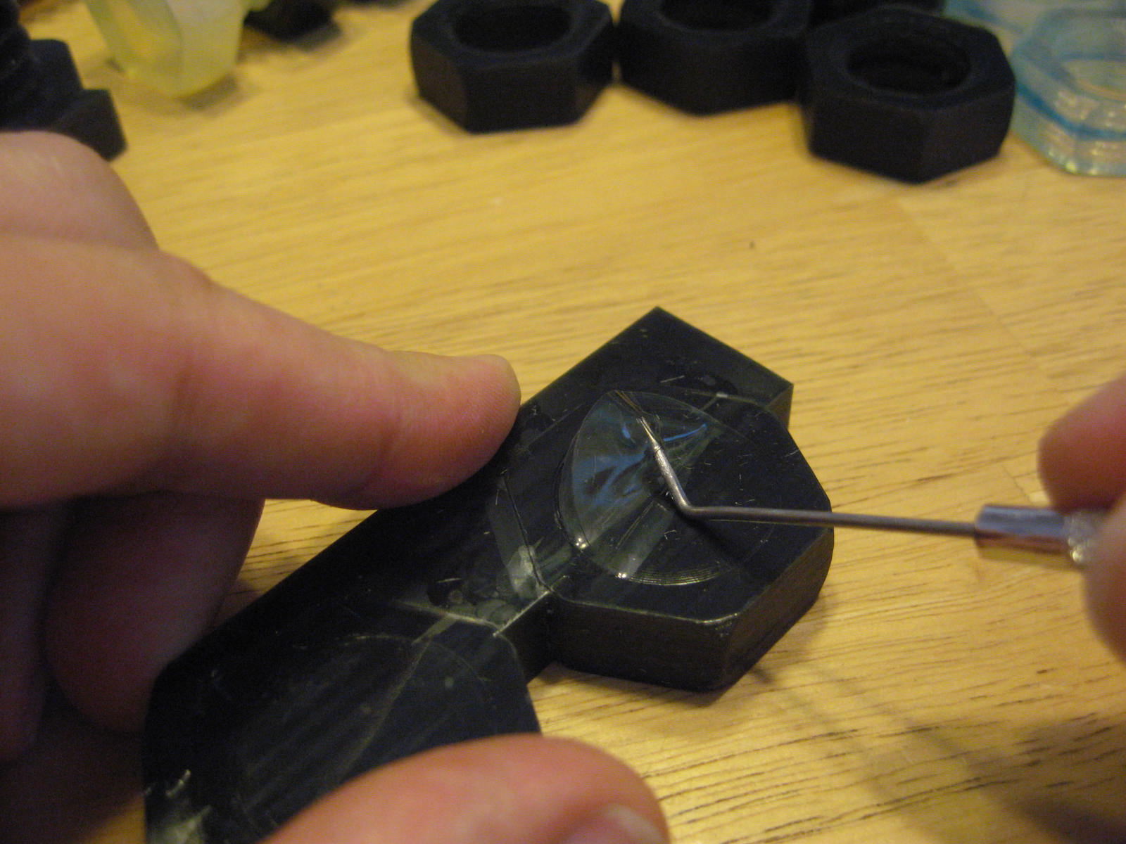
Solido provided strong forceps to help peel away material. Those forceps are great for most models, but they're awkward for cleaning material from holes like these so I bought a set of hobby probes.


The probe's sharp point stabs neatly through several layers of unused material in the hole. Tipping the probe lifts the material so it can be pulled away.


Once the ends are free, the material can be pried out by hand.


The layers of extra material have been glued together in a chain. But these layers didn't just pull out freely; I carefully tugged at the edge of each sheet to tear out the next one, one-at-a-time.


Sometimes one layer of support material tears free of the next, so it's necessary to insert the probe and pry the next layer loose before continuing the chain.


After clearing the holes, I removed the rest of the support material from the outside.


Most observers notice there's a high proportion of unused material in each build, which is true. It's roughly like a CNC mill that custom-builds a block for each model, building up the layers additively and then peeling them away material afterward. But it's generally economical because the process is energy-efficient and uses raw material that costs 10 to 15 times less per unit-volume than other 3D printers in its price class. Nevertheless, the cost per model can vary widely from one sample to the next depending on how efficiently the material is utilized.


The SD300 can't directly re-use the leftover material, but it's recyclable as PVC scrap (recycle code 4) by bagging and tagging it and delivering it to a commercial recycler. It can't go with household recycling, so I collect the SD300's scraps in a separate bin. It could also be discarded as ordinary trash since it doesn't contain anything harmful.