Tuesday, December 7, 2010

Cooksey Maze rings in regal style

I built a set of rings for the Cooksey Tribute D puzzle cylinders from my previous post. I put layers of black material at the top and bottom of each ring to match the puzzle cylinders by changing the PVC roll while the SD300 was building the model. The black accent gives it a nice touch.

I pulled the support material out of the holes first, just like I had with the cylinders.


After the holes were clear, I peeled away all the external support material to set the rings free.


I also treated the rings with Weld-On 2007 to improve the sidewall transparency. The ring at left is un-treated, the one at right has been treated.

Saturday, December 4, 2010

Deep, deep holes & Oskar's Cooksey Tribute D

I've previously mentioned Oskar van Deventer's Cooksey Tribute puzzles, a series of six puzzles inspired by a premise by Robert Cooksey. I encountered an apparent error in the puzzle while trying to solve the fourth in the series, Cooksey Tribute D.

Oskar confirmed there had been a minor error, and graciously allowed me to 'print' my own replacement copy. Due to the width of the PVC material I discovered I could build two puzzles for exactly the same material cost as one. In fact, I could build three for the price of one if I built two of them upside down.


As usual, the models emerged surrounded by a solid cocoon of support material, which needs to be peeled away. The Cooksey Tribute D puzzle is supposed to be a hollow cylinder, so I concentrated on pulling the material out of the holes before I peeled away the external material. I figured it'd be easier to handle this way.


The hollow interiors are really deep and really narrow, so I couldn't pull out the support material with my fingers. Before long the only tool that could reach into the hole was a probe I'd bought at my local hardware store.


As it turns out, the probe was the perfect tool for hooking into the X-shaped peeling cuts in the support material. This was an unusually challenging job because the holes were 11 cm deep, with 650 layers of support material. Luckily the probe made relatively quick progress, snagging several layers at a time.


When the holes were finally cleared, the block looked like this. It reminds me of a part from my '75 Scirocco's exhaust system. (I don't really miss that car.)


With the hollow interiors cleared, I began the easy job of peeling away the external supports to free the models.

Wednesday, December 1, 2010

Rattleback twins

On Tuesday evening I saw a model of a Rattleback posted on Thingiverse. A traditional rattleback reverses direction when it's spun in a clockwise direction.

I made two models, one with the mesh reversed so it would respond to a counter-clockwise spin. Unfortunately the models were too 'tall' so they tended to tip over instead of spinning. A conventional rattleback, at lower-right, is only half as thick.


Since the model was just too thick, I used SDMove (the SD300 build software) to reduce it 45% in the Z axis and built another set. The new model, shown in red, was much more functional. But it had a flat spot due to the layers in the Z axis, so it wasn't as good as it could be.


So I built a third set using the same mesh, but oriented it to be built on its long edge. This exploited the SD300's excellent XY axis resolution to give smooth, curved contours. (FDM users employ the same strategy.)


Now I've got a left-handed and right-handed pair of rattlebacks, one which reverses clockwise and the other counterclockwise. They're still not optimized, but it's probably as good as it gets by just tweaking the mesh rather than re-contouring the source data.


I uploaded the modified meshes back to Thingiverse for the benefit of other users. Maybe someone will refine it further.

Thursday, November 25, 2010

Basic Male Form by Nicholas C. Lewis

Nicholas C. Lewis uploaded a model Basic Male Form to Thingiverse just as I was starting a build that had a little unused volume in it. On a whim I downloaded his model and scaled it to fit. It fit neatly into the leftover volume, so I got an extra model without using any additional material.


His original was 10 cm high, but I scaled it down to ~2 cm to fit within my existing build envelope, so I got a very tiny but very detailed model from the SD300.


It looks pretty on my $3 light table from American Science and Surplus. It's amazing how easily I can build an extra model for so little effort.

Sunday, November 21, 2010

"Snap" assembling a Nut

I never seem to have the right fasteners on hand for my projects, so I like to design things that can be assembled without screws. This nut-themed shell is designed so two identical halves can snap together, leaving ample room for the mechanism inside.


For testing, I assembled two halves without installing the mechanism. The part was built with a combination of opaque white material and transparent material, which makes it striped.


The round bumps will fall into matching holes when the part is squeezed together. This is a very rigid part with thick walls, but the SD300's PVC material has just enough 'give' to allow these halves to be snapped together securely.


Thanks to the layers of transparent material, the assembled shell includes windows through which the mechanism will be visible in the final puzzle.

Sunday, November 14, 2010

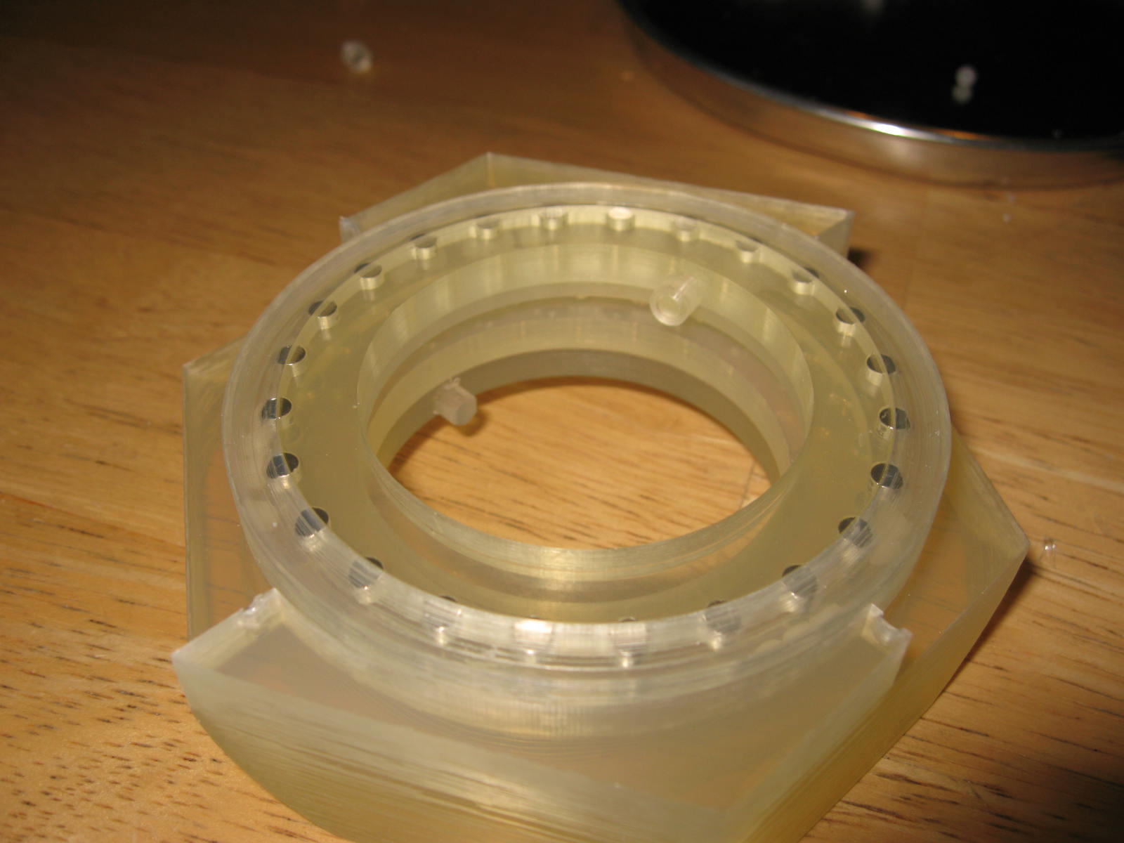
Magnet bearings

I've wanted to develop this, even before I owned an 3D printer.

Oskar's 8-Inch Bolt is a cylindrical incarnation of a hysteresis maze, where the user can move a collar up or down but can't turn it from side to side. The collar has a pin that traces from side-to-side along the walls of a maze, but the user can't steer it. There are very few samples of the puzzle in existence.

I liked the premise of Oskar's 8-Inch Bolt, but the collar operated very poorly due to excessive friction. Sometimes I tried to share the puzzle with other puzzle enthusiasts, but it moved so roughly that only one could even make it work. So I've been developing a low-friction replacement collar.


I designed the replacement collar as a disc studded with 24 magnets, which would be sandwiched between two additional rings of magnets. The magnets are all configured in repulsion, so the central disc tends to hoover. This minimizes friction, yet the magnetic repulsion ensures the ring won't rotate unless it receives some lateral force.


In later prototypes I added a channel with nylon ball bearings so vertical forces won't cause the disc to rub against the other parts. (Nylon is unaffected by the powerful magnets.)


The current prototype seems to exhibit exactly the right behavior. The central disc effortlessly rotates in response to sideways pressure on the pin, but it stops at predefined positions and stays put.

Monday, November 8, 2010

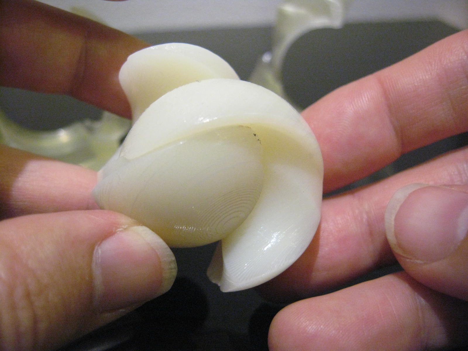
More marbles?

Maybe I'm stuck in a rut, but I've built a substantial number of test marbles using various build orientations, color schemes, and tolerances.


Some are twisted in the reverse direction. I plan to use them as building blocks for a larger puzzle by gluing some halves back-to-back so they have to be attached to other parts in a specific way.


Despite all the different tolerances, the pieces are similar enough to mix-and-match. When two halves are joined into a single marble they usually hold together firmly, but some pairings will spontaneously disassemble themselves as captured in this video.

Saturday, October 30, 2010

Isolated Marble, rev 2

I refined the curves and angles in yesterday's Isolated Marble prototype and built another today. I gave the model a black stripe to distinguish it from the previous model by changing to black material for 6 layers part way through the build.


It works better than the previous revision, but it reveals more details that need refinement.


The curve was supposed to be smooth, but it exhibits a rough texture like a washboard. That's not a build problem, it's an interference pattern in the source data. A silly mistake, but it'll be easily fixed.

Friday, October 29, 2010

Isolated Marble, a work-in-progress

Some time ago I tried to develop a variation of Bram Cohen's Trapped Marble puzzle, which is now being sold by Hanayama Ltd as Cast Marble. I tried to modify the cuts as radically as possible, but the puzzle as a whole behaved just like Cohen's original. It apparently lacked novelty, so I stopped working on it.


The challenge in Bram Cohen's original puzzle was to assemble all four pieces; there was no challenge assembling the two-piece marble without the rest of the puzzle. But in the following months, many people have been confounded by the central 'marble' from my prototype. It just doesn't go together as people expect.


The secret to assembling the marble by itself is to withdraw the parts farther than you might intuitively expect, until they elegantly nest and join together. My four piece prototype had been designed to be assembled from a widely-separated orientation, but I hadn't anticipated the two central 'marble' pieces would retain this behavior without the other two pieces. It turns out to be a satisfying puzzle all by itself!


So I've begun exploring designs for a two-piece marble puzzle. To help distinguish each batch of prototypes I briefly installed red PVC for several layers in the middle of the build, which gave these parts a red stripe. For subsequent prototypes I will try swapping-in small amounts of other colors, again to uniquely identify each build.

Thursday, October 21, 2010

Built-in color graphics

This weekend I built some parts with shiny, colorful graphics built-in.


I embossed a thin extrusion of a heart-shape, 0.17mm thick, onto the tops of four parts. For building, I arranged the parts on the table (not as shown) with the embossed graphic parallel to the build platform. (The SD300's build software has a 1-click tool to do that.)


I built most of the model in white material, then switched to red material for the last layer. Hence most of the model was white, but the embossed heart shape was built using red. The excess red material simply peeled away with the supports, leaving the red graphic integrated into the model.


The finished parts have the colorful heart graphic integrated right into the model. Unfortunately, red is the only SD300 material that seems to offer enough contrast for this technique. The "black" material isn't dark in thin sections (but I'm working on a workaround). Solido lists "blue" material for the machine, but dealers don't have any inventory.

Saturday, October 16, 2010

Clearing an X with a probe

It's occasionally handy to have a set of general-purpose probes at hand for cleaning support material from small openings and crevices. They aren't needed for most jobs, but they're invaluable for a few situations.


This model had two blind holes, which I filled with X-shaped peeling cuts. I made sure the cuts didn't touch the walls in order to avoid splitting the material into sections.


After building, the X marks identify the material that needs to be removed from the holes.


It was too awkward to reach inside the holes with the standard tweezers, as there just wasn't enough room to operate the jaws. But the probes are perfect because the thin point can hook under the X. The probe's point is small but not sharp, so the slightly blunted tip doesn't scratch the model.


The X disappeared after the last layer of support material was removed, visually confirming the hole had been cleared completely. When I had used tweezers for similar jobs I'd always scratched or gouged the bottom of the hole; the probe worked much better.

Saturday, October 9, 2010

X Marks the peeling cut

In one of my first posts I suggested running a peeling cut through holes to give the forceps something to grab onto when peeling away the supports. But it's not so good to run a cut through a large hole (or hollow area) because it divides it into two sections, which could take twice as long to peel. It also reduces the size of the Z-folds, so the support material is more likely to tear instead of coming out cleanly.

So I've begun adding an X-shaped peeling cut inside hollow areas, not touching any walls.


At first the X-shaped cuts don't look useful because they don't touch any walls, which goes against the standard convention for peeling cuts. But they conspicuously identify the leftover support material.


The X provides a convenient location to grab the support material without touching any walls, thereby preventing the forceps from scratching the model.


The Z-folds work better because all the sides are clear of peeling cuts. Even if the material tears during peeling, the X provides a safe place to get hold of the remaining layers and begin peeling again.

Wednesday, October 6, 2010

FInally, my second failed build

Ordinarily, the SD300 tests the integrity of the XY cutter at the completion of each layer by using the cutter to separate the model from the material and then attempting to rewind the material onto the source roll. When a cutter is worn out the material remains attached to the model and the machine emits a distinctive noise from an internal clutch.

The machine had a relatively new XY cutter, so I was surprised to hear the slipping-clutch noise which usually indicates a worn out cutter. The machine's log seemed to express the same astonishment, "the cutting knife is new and the previous layer was OK." Evidently the SD300 concluded the XY cutter was too new, so it just tried to continue building the model until I intervened.


Normally the machine can continue to build the same model after the XY cutter is replaced, but inspection revealed this model was full of air bubbles. The glue hadn't been spreading properly so the layers weren't welding together. This model would be defective, even if the rest of it built perfectly.


I ran some tests which confirmed the culprit was the XY knife, not air in the glue system. I've had other knives wear out, but this was the first occasion where it caused any problem with the model being built. Evidently it had scraped the model surface, creating gouges and voids which prevented the glue from spreading between sheets. Everything worked when I replaced this cutter (shown below) with a new one.


Frankly, I'm pleased to have only two failed builds since I bought the machine in February. That compares favorably with colleagues who use V-Flash and Dimension modelers.

Admittedly I've had bad builds for other reasons, such as bad STL designs or improper layouts, but only two builds have been defective. My first defective build was entirely my own fault, as I'd allowed the glue to run out. This one might have been a freak incident.

Wednesday, September 29, 2010

Too thin?

Yesterday I encountered a puzzle designer who'd shared a rough draft of a model with impractical, thin walls. The pictured model is only 19mm high, with many 0.63mm walls and several tapers that were even thinner.

I'd tried to avoid thin walls in my earliest designs for the SD300, but occasionally built thinner walls by chance or miscalculation. Some worked, some didn't, but I always learned something new. So I got permission to build the model, fully aware I was going to have problem with it.


Unsurprisingly, lots of really thin areas broke away while removing the supports. I managed to preserve some walls as thin as 0.5mm by peeling the support material away slowly, one layer at a time. Some undercuts were so narrow I couldn't even reach into them with my curved forceps.


Still, the model emerged sufficiently intact for examination. The channel walls were so thin I could barely get a fingernail inside, and they were noticeably flexible. I dipped the parts in Weld-On 2007, which immensely strengthened the surviving structures.


Surprisingly, the parts can be assembled...barely! The tolerances were inadequate, but they just barely functioned because the channel wall flexes just enough to compensate.


The design doesn't make provision for installing all four parts, so I couldn't assemble the whole puzzle. But it's impressive that it worked at all.


These parts aren't practical due to the overly-tight tolerances, but the model confirms the designer's concept nevertheless. But I certainly wouldn't try to build such thin walls routinely. A comparable model might take 10 minutes to clean away the supports, while this took almost 2 hours. If it hadn't been for the Weld-On dip the parts probably would've broken during testing.

But it shows that the user can venture outside of "good practices" at his discretion. The SD300 will attempt to build any geometry it can process, even if it's not practical. It's the user's choice.