Monday, April 26, 2010

Comparing with SLS and PolyJet

I uploaded my spherical 2x2x1 puzzle (the 'practical' one) to Shapeways and tested some samples built in other materials. (It's available for anyone to purchase.)


The parts built in nylon SLS (left) were functionally identical to the PVC parts built on my SD300 (right). In fact, they were interchangeable. Both materials tolerate the flexing that's required to install the last piece.


In contrast, a part built in Objet "PolyJet" (left) arrived already broken. Although the PolyJet Fullcure material claims to withstand bending, it's apparently brittle at this 1.6mm thickness. The SD300 part (right) is sufficiently strong because the posts were built in a horizontal orientation.


But the PolyJet puzzle is sufficiently intact that it works okay, despite the broken piece.

Sunday, April 25, 2010

Impractical parts again

As an exercise I had previously built the part sketched in gray, although I'd expected it to be impractical on the SD300. The colleague who drew the sketch asked me to build the rest of the parts, the 3 identical yellow ones, because he wanted to see what they would look like.

The parts came out looking nice, but it was immediately clear there would be no way to assemble it because the cavities need to nest too tightly together. That had been anticipated in a discussion thread some time ago.


But it inspired me to split all the parts in two halves, connected by round pins that fit into square holes (like early Lego toys).


This enables the parts to be assembled in two symmetric halves, where each half proudly exhibits the contours from the original sketch.


These two halves fit together to form the original 2x2x1 puzzle in the sketch. It fits too tightly for actual play, but it's a nice tangible demonstration of the original concept. I'll mail it to the author of the original sketch as a nice souvenir.

Saturday, April 24, 2010

Printing directly onto PVC

Mechanical puzzles often call for tiles, decals or stickers to distinguish the parts. (Think Rubik's Cube.) The SD300 should be able to create tiles of any desired thickness, so I cut a sheet of shapes suitable for a puzzle I built last year.


One of the tiles is supposed to be labeled with the puzzle's name. I used this custom-made guide to hold one of the tiles in my printer's CD-loading tray. (The tile is barely visible in the slot nearest the 'TOP' label.)


The printer uses delicate pigment-based inks, so I printed on the back side of the tile so the text would be viewed through it. This will protect the pigments after the ink dries. (Note: You can only print on plastic using a pigment based printer. Most ordinary ink-jet printers use water-soluble dye-based inks, which probably won't work on PVC.)

Sunday, April 18, 2010

2x2x1 perfect refinement

I continued to refine the 2x2x1 puzzle, thanks to the SD300's ability to churn out a working model in under 4 hours. For my third revision I added two posts to the globe in the middle.

Due to a goof I built the posts only 1.7mm thick instead of an intended 3.4mm, but this turned out to be a happy accident as they're quite strong after solvent treatment. (Radius, diameter, whatever...!) They were built parallel to the build plane for maximum strength.


The posts both stabilize the moving pieces and restrict them to moving around the center axis. This third model worked better than its predecessors, but it was still fairly easy to pop the puzzle apart when the parts were slightly turned off-axis.


So my fourth revision adds caps to the posts, in a shape that locks into the spherical cavities in the moving parts. That way the post should restrict the parts to axial movements and the cap should hold the puzzle together.


Here's a side-by-side comparison of the third and fourth models partly assembled.


The fourth-revision puzzle functioned perfectly after assembly. The PVC has just enough flex that I had no trouble gently pushing the parts together, but the new caps are secure enough that the puzzle doesn't readily come apart...even with effort!


Here's a picture after adding colored stickers to identify the sides. Just for novelty, I left the top & bottom uncovered to expose the mechanism through the transparent surfaces.

Friday, April 16, 2010

2x2x1 refined in one more day

Yesterday I thought of a simple puzzle, sketched it, and built a quick test model. It was very convenient, and I was pleased at having a physical sample. The model was functional but it needed refinement because it tended to come apart unexpectedly. So today I revised it using the first sample for guidance.

Out came this second model...


The parts on the left are yesterday's model. The parts on the right were revised to include a central globe that stablizes the other parts, among other revisions. When assembled, the revised model doesn't come apart like the first.


I recorded a short video to compare the two models. The second model still has a few flaws, but I couldn't have refined it so quickly without the SD300.

Thursday, April 15, 2010

A 2x2x1 puzzle in about a day

The "Impractical Geometry" in a previous post was a visualization model for a puzzle that had been conjectured on a puzzle forum, here. Yesterday I was suddenly inspired by a practical, simple mechanism by which that particular puzzle could be built. When I came home, I threw together a model, exported it to Solido's SDView application, sent it to the printer, and let it build overnight.


I expected the parts would need additional work to make them practical, so I didn't bother with fillets and tolerances. I just wanted something I could look at while refining the model. They look nice, though.


The premise is that one part has a truncated spherical shell exposed on one side. The other three parts have spherical cavities that fit over the exposed shell and a spherical hook that reaches inside. I was surprised to discover how well they fit together.


With very little effort, all four parts snapped together and stayed together. It turns a bit like a truncated Rubik's cube. It's shown below halfway through a turn, and the parts move smoothly enough to confirm this mechanism is practical. Talk about instant gratification!

Sunday, April 11, 2010

Barrel puzzle, now functional and tinted

In a previous post I got the barrel puzzle working by dipping it in welding solvent. But it isn't really a puzzle unless there's some way to distinguish the parts. Ordinarily I would cut and apply vinyl stickers.


But some colleagues admired the semi-transparent appearance, which would be hidden if I applied stickers over the surfaces. I experimented with several alternatives before getting an inspiration today.


I dusted the parts with Jacquard Pearl-Ex pigment, choosing "interference" colors that aren't visible unless light reflects off the surface at just the right angle. Then I misted the surface with Weld-On 2007 to embed the pigment permanently into the PVC. The puzzle in all these pictures has been tinted, but the colors were hidden in the pictures above. Below, the color is revealed when the light is just right.


Now it's possible to mix up the colors, creating a challenge to get them back to their original positions. (Like a Rubik's Cube, but simpler.)

Saturday, April 10, 2010

Embedding artwork inside a 3D block

Since the SD300 builds models inside a solid block, the act of peeling away support material often gives a surreal sensation as a solid shape emerges. Like the face of this tiny 3D portrait gradually revealed below.


The peeling process inspired me to build this inverse model, based on the same tiny portrait, in which the face appears inside a solid one-inch cube.


The face is a hollow space inside the solid cube.


A more subtle variation builds the whole cube as solid material. Instead of a hollow face, I rendered it as a shell of interference patterns. The cube looks almost clear under ambient light, but intense light reflects off the internal cuts, revealing the ghostly 3D face within.

Tuesday, April 6, 2010

Impractical Geometry, round 2

I bought two additional pairs of forceps after my experience peeling 'impractical' parts.

At top is the original set of forceps supplied by Solido. It's the most generally-useful of the bunch, with strong wedge-shaped jaws whose knife-edge slides easily between layers. Its jaws close flat, so it can spread force on a tightly-gripped sheet without tearing it.

The second set is an Xcelite 434 sharp-pointed tweezer. The point is useful for stabbing PVC material and applying sideways force to clear overhangs. The jaws are gently curved to concentrate grip at the end. It's prone to damage the part (and work surface, if dropped) but it's got special uses.

The bottom set is an Xcelite 7V with slender, curved jaws that can reach concealed areas through small openings. It can't grip as firmly as the other pairs, but it can reach places straight tweezers can't go.


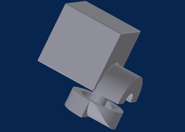
The deep overhangs and hollow areas had been so difficult to clear last time because there wasn't enough free space to maneuver the material. This time I added wedge-shaped peeling cuts so I could pull material out of the part's openings, thus giving me room to reach in and work on the waste material embedded inside.


After building the part, I concentrated my attention on clearing material out of the wedge-shaped channels.


It took a few minutes, but it worked quite well. With this wedge-shaped opening I already had access to the interior of one of the overhangs.


I used the pointed tweezers to loosen material in the overhang, then used the curved tweezers to reach in and pull it out. The curved tweezers can't grip very tightly, but I learned to gently work the waste material back and forth until it gently broke free.


Unlike last time, the part emerged without any blemishes or rough spots. It took about 35 minutes, so it's not quick work, but it was much easier than last time.


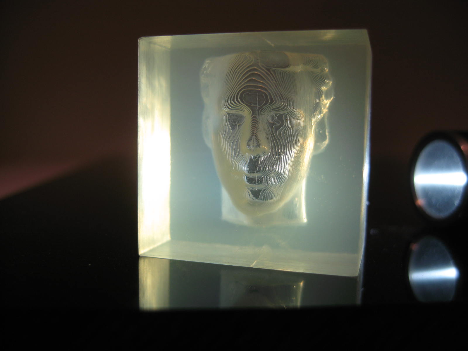
I dipped the part in Weld-On 2007 to improve its transparency. I had overlooked a small piece of scrap material inside one of the cavities, visible through the sidewall in this picture. Unfortunately, the solvent dip permanently welded the scrap inside there. It's important to clear away all scraps before using any solvent!

Sunday, April 4, 2010

Impractical Geometry...could be practical

The SD300 isn't so convenient for building parts with deep overhangs or hollowed-out areas because all the support material has to be pulled out through existing openings. But I've been practicing with increasingly ambitious parts so I decided to try my chances at this visualization model I designed last year. It's got deep overhangs and very small openings so I expected a lot of trouble, but I hoped it would be an interesting learning experience.


It was easy to remove the external material, as expected, but the internal material was harder to reach because the manufacturer-supplied forceps could barely fit into the openings.


Despite the challenge, I got all the material cleared away without damaging the part beyond a few cosmetic blemishes. Based on what I learned, I could probably do better by buying some bent-tip forceps from Xcelite to reach the difficult places.


I'm glad I built it. It's a great visualization model thanks to the transparency. When I shined a light through the part I could see a lot of internal details that had been difficult to view on the computer screen.

Saturday, April 3, 2010

Process comparison: SLS

Here's a part that includes an edge that tapers down to 0.10mm in thickness, far thinner than most 3D fabrication processes are rated for. I had copies built by Invision HR, SLS, and my SD 300 and compared how they handled the thin taper.

At left, the blue part was built by an Invision HR. It truncated the taper before the end, and the portion it built was brittle so the leftmost taper broke off. But this isn't a fair comparison because the part was built in a vertical orientation, so the build didn't take advantage of the Invision HR's excellent Z-axis resolution.


The SLS part was built in bright white polyamide. It was difficult to get a picture of it, but you can see the thin tapers were built to their full length. My caliper measures the thickness as 0.19~0.23 mm, about twice the thickness specified in the STL file, but the tapers are sufficiently tough that they can survive handling. But the nylon exhibits signs of fatigue after flexing, suggesting it would eventually break.

At right, the SD300 built the thinnest part of the taper to full length with a measured thickness of 0.16~0.17 mm. The taper is thinner and more-flexible than the SLS part, but it's tougher too. It showed no fatigue after flexing, which isn't a surprise: it's basically just a single thickness of PVC sheet. But elsewhere, on the top of the curved 'foot', the top sheet of PVC would probably peel off if it was exposed to much use.


That weak spot presented a good opportunity to test the effectiveness of solvent-finishing, which I discussed in my last post. I dipped the part in Weld-On 2007 and tested it against an untreated part. I put both parts into the cavity for which they'd been designed to fit and put them through mechanical tests. Afterward the untreated part showed some wear, at left in the picture below. The weak layer is still attached, but it's peeling. The solvent-dipped part at right is in good condition, exhibiting no signs of wear or damage.