Friday, July 29, 2011

Yoshimoto experimentation

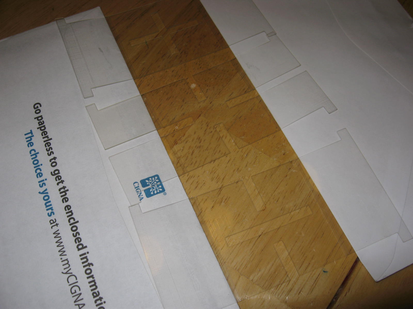
In July 2010 I saw plans on Thingiverse for building a kit that could be assembled into a Yoshomoto Cube, which is a type of folding puzzle. At that time I didn't have much experience with hinged models, so tried to adapt the concept.

I built a pair of experimental models that had hinges in each axis, some horizontal some vertical. This picture shows the two models before I'd finished removing all the support matieral; they look like they're attached, but I subsequently separated them.


One separated, the models could fold along the hinged connections. They were somewhat delicate (and tiny!) but each could be folded into many shapes just like a Yoshimoto cube.


Careful folding and unfolding would permit the model to change shape until it was inside-out from its starting position. The model on the left has been inverted, while the one on the right has been returned to its starting position.


Also like a Yoshimoto cube, the inverted and non-inverted models could be nested together in such a way that the combined pair could still be folded in all the same ways as before.


After a few hours' of use both models broke along one of their vertically-oriented hinges. I didn't continue with the project at that time...and now a year has passed by.

Recently I've gained a lot of experience building models with built-in living hinges, so I want to try experimenting with the Yoshimoto cube again soon.

Thursday, July 21, 2011

Flexible Burr...Cuburr?

Here's a picture of the current revision of my flexible burr puzzle. I've adopted a scheme with a distinct color for each type of part.


Assembling the parts depends heavily on the flexibility of the material, as the parts must be distorted to fit through each other.


It looks like a mess, but the puzzle is almost solved.


The last step is to fold the faces flat and hook the corners together so it holds a cube shape.


I carved the puzzle's name "Cuburr" into one of the faces in the 3D data, which caused the SD300 to trace it like line art.


That last trick exploits a limitation of the SD300's build process: in the STL data the letters were rendered as cutouts in flat wall, narrower than 1 mm. The SD300's XY plotter can cut with 0.1mm precision, but regions narrower than 1 mm are left bonded to the layer beneath; you have to pry them mechanically if you want them removed. For situations like this, it's a convenient way to emboss line art onto a flat surface.

Thursday, July 14, 2011

A flexible burr puzzle

(7 Feb 2013) I notice some debate about this post elsewhere online -- if you have questions feel free to leave a comment or contact me via the email address in my profile (right).

 
In 2002 George Miller devised an unusual puzzle titled Three Card Burr, made by laser cutting slots into three ordinary playing cards so they could be interlaced together. Interestingly, there's no practical way to disassemble the cards after the puzzle has been solved.


I was inspired by George Miller's Three Card Burr puzzle to create a more complex puzzle to exploit the SD300's ability to build sheet-like structures by creating a 3D model whose geometry can be mapped to the build material. I designed this flat model whose middle section is nominally 0.51mm thick, so it will be built using three thicknesses of 172-micron PVC sheet. The adjacent areas have two 0.34mm thick panels stacked one above the other and attached to the middle section by a 0.17mm thick strip to act as a hinge. The whole model is about 120mm x 70mm x 0.9 mm.


Here are my first 3 sample models, built in transparent material.


Like Three Card Burr assembling the puzzle begins by carefully interlacing the sheets together. It wasn't as difficult as I'd expected because the resiliency of the PVC material enabled me to flex the puzzle without tearing it.


Once the pieces are interlaced together, the hinged panels fold out and interlock at the corners to form a cube. This part was far more difficult than I'd expected because each corner depends upon its neighbors for stability, which meant each corner would come apart when I tried to assemble the next corner. I'd forgotten to allow for the thickness of the material in the corner dimensions, so the panels warped from excess tension.


Not bad for a first try, though. It proves the concept is basically sound; now I just have to adjust the dimensions and add something to make the corners more stable. Maybe a small tab or hook?

Tuesday, July 12, 2011

Eurofighter

Solido provided a sample model that demonstrates an interesting way to exploit the flexible PVC material. The model prints out as a number of flat, semi-rigid parts with living hinges and flexible tabs.


Fold the parts at the hinges and pass the tabs through openings in another piece.


These tabs tuck securely into the underside of the wing piece, thereby snapping the pieces together.


When all the pieces are assembled in this way, you get a modernized plastic version of the good old 'paper airplanes' we used to make from paper.


This gives me some fresh ideas for foldable models!

Tuesday, June 28, 2011

Assorted "stuff"

I'm continually building models and often forget to share them, so here are pictures of some recent projects.

I built a three-piece puzzle in transparent plastic. While it was building I used a permanent marker to add three splashes of color between layers, using the technique from an earlier post.


Once assembled the transparent material catches the light and the colors seem luminous!


I built this simple-but-elegant Mini Stand for iPhone & iPod Touch. While it was building I switched between black and white material to incorporate a subtle, decorative stripe. It's a small model so I built 3 of them side-by-side using no more material than just building 1.


A Thingiverse user created a script for Duplicating House Keys using the free OpenSCAD tool to create the model data. But it only makes keys for old Kwikset KW1 lock cylinders, so I think it'd be interesting to update the script for the newer KW10 models.


This Recursive Reuleaux Triangle is the first model I built that was pre-assembled. The parts were built already-interlocked in grooves so the triangles can slide around freely but they can't come apart.


Pixobox Studio provided the data for this detailed figure of a Human Head. I had reduced its size to 28% to fit it within volume left over for another model I was building. The Z-axis layering is plainly visible at this low resolution, but it has excellent XY surface detail. There's some tiny text on the sidewall, just below the chin.


Here's a view of the back of the statue, showing the surface details in the hair and more tiny text carved into the back wall of the figure.


Last month I ran into a challenge trying to disassemble part of my car. This spring needed to be tightly compressed to open another access panel, but it's offset from the opening where it's awkward to reach with ordinary tools. So I simply built my own tool with the SD300.


So I 3D printed this simple plastic tool, which has two built-in elbows that reach around and compress the spring. The tool has 1cm thick walls, so it was extremely strong...which was lucky because I had to be surprisingly forceful to release the spring completely!

Tuesday, June 14, 2011

Building hollow parts "as solid"

Unlike most other 3D printers, the SD300 builds solid parts faster than hollow ones of the same size. Hollow parts require just as much material as solid ones, so I generally make my designs as thick and solid as I like.

But I know many designers who optimize their designs for Shapeways White Strong & Flexible material, so they typically design hollow parts with very thin walls to minimize costs. The SD300 isn't very suitable for very thin freestanding walls, but could I build such models if I just left the support material embedded inside? Would it sacrifice functionality or strength?

A colleague graciously lent me a set of STLs that had been optimized for the EOS with exterior walls only 0.8mm thick and I set out to build them with peeling cuts arranged to leave the support material trapped inside.


I built a small batch of test parts without any trouble. Because the support material is trapped inside they feel like ordinary solid parts, but they aren't quite as transparent as solid parts usually are. The interiors are somewhat cloudy, undoubtedly because the SD300 cut and masked the material inside to facilitate removal. They looked perfectly acceptable, although I have my doubts about their durability.


It went well enough that I tried another batch, then another. A big piece broke off while I was peeling the last batch of parts. The chip (at top right) is still attached to the support material, and the pin is pointing to the surface where the chip broke off. If you look carefully you can see the thin, triangular border which was the only region that had held it together. Not surprising, really.


I repaired the break by putting the piece back and running welding solvent (Weld-On 2007) over the model. The solvent helped glue together the surface of the model, but the support material remained safely un-bonded so it could still be peeled away. Apparently the SD300's Anti-Glue coating works against Weld-On.


I test-assembled some of the parts; they didn't fit together as accurately as parts built from solid STL data. That makes sense in hindsight. Using "hollow" STL data meant the interior material wasn't continuous because the SD300 had made cuts for the interior walls and had masked the interior layers with Anti-Glue.


So the experiment answered my basic question, could I build STLs that had been optimized for EOS or other thin-wall technologies? Yes, I could build test models with restrictions on their usefulness:
  • The support material would have to be left inside, so hollow STLs built as-solid would be much heavier than a hollow model built on an EOS.
  • Such models would not be as strong as solid models, despite their solid appearance, because the interior isn't bonded together like solid models.
  • Such models aren't as dimensionally accurate as models build from solid STL data.
  • Such models aren't as transparent, even when built with transparent material.
If I intend to build parts on the SD300 I would not design them with thin walls like these, but the technique is potentially useful for verifying the basic size, shape, and dimensions of STL data that's optimized for another build process.

Wednesday, June 8, 2011

Efficient peeling cuts revisited

Here's another example of how to arrange peeling cuts for efficient cleaning of an SD300 model. The user adds peeling cuts (the purple walls) while preparing to build models in the SDView software. Peeling cuts don't affect the model, but they instruct the SD300 to cut the support material that surrounds the model so it can be torn away conveniently.

When I had just learned to use the SD300 I tended to put peeling cuts between each individual model to isolate them, resulting in lots of small areas that had to be cleaned one-by-one. But I eventually learned to arrange models so the peeling cuts could be joined and streamlined, peeling several models at once.


These nine models have two continuous peeling cuts that follow the geometry, so the two exterior regions can be peeled away in an easy continuous motion.


After the two outer strips have been removed the models are still connected by leftover support material between them. Much of this can be peeled away in the same manner, as the top and bottom areas are continuous just like the other strips were.


There's still some support material embedded in the middle layers between models, but it doesn't have to be removed layer-by-layer like the other strips. Instead I just loosened up the support material by squeezing a probe between layers in several places...


...then I gripped two adjacent models and gently twisted them to-and-fro, which gradually loosened the support material between the two adjacent pieces. In about 10 to 15 seconds the leftover material was loose enough to free the two adjacent pieces, and I moved on to the next pair of embedded models.


All told, it took less than ten minutes to completely clean these models. The same batch of models probably would've taken a half hour or more if I had isolated them with individual peeling cuts. Back when I was just learning to peel and clean models it probably would've taken over an hour, so experience helps too!

Thursday, May 19, 2011

Splice in the feeder?

When there's about 1-2 meters of material left on a PVC roll the SD300 usually stops and asks the operator to replace the materials. After removing the used roll I recently noticed what appeared to be a double-thickness where two sheets of PVC were spliced together. I believe this is how all kinds of rolled media are typically manufactured such as paper, tapes, newsprint, etc. I guess the SD300 is programmed to leave a little bit of material on the roll to avoid pulling a splice through the feeder into a model. But could it happen anyway?


I had a weirdly malformed build last June. Now I wonder if it was caused by pulling a splice into the model?

When I'd partly peeled the model there was a giant gap in the support material (right) and the model was slightly split. The model was otherwise okay so I didn't worry about it, but luckily I saved some pictures.


More evidence.

While peeling that model I found a piece of leftover support material that seemed to have a double-thickness along one edge. Was this a splice? It seemed odd enough that I took a picture of it.


The SD300 software archives all the machine's activity so I went back and reviewed the 7 June 2010 logs. (I knew when it occurred thanks to the date on the pictures.) There were several new bits of evidence:
  • During the build I had paused the SD300 at layer 41. I think I remember putting in a low PVC roll to use it up.
  • At layer 50 it had used up the entire roll and pulled the end of the material into the feeder, causing the feeder to jam. I'll bet it had pulled the splice into the model at this point.
  • At layer 51 the cutting knife broke. It was a well-worn knife so the breakage wasn't unexpected, but I'll bet it got broken by the splice in the previous layer.
  • At layer 68 the iron bridge unexpectedly moved on the Y axis, causing an error. I don't really understand the significance of this, but that's the only time it happened in over 600 logged builds.


Mystery solved 11 months later?

Maybe. Regardless, I learned several useful principles from reviewing these pictures and logs:
  • Don't reload a nearly-empty PVC roll. The SD300 needs to build many layers before it can accurately calculate how much media is left on the roll, and a low roll could run out before that. Saving a few meters of PVC isn't worth ruining a model or breaking a cutting knife.
  • If the SD300 does completely empty a roll, check to see if a splice got pulled in. It's probably not common, but I would've cancelled the build if I'd seen it.
  • When a cutting knife breaks inspect the model to see if there's anything irregular. The breakage might have been caused by an unusual bump or bubble.

Saturday, May 14, 2011

Animated Geek Campfire


When I started using my SD300 last year I enthusiastically downloaded a number of models from Thingiverse just for the satisfaction of building a variety of models, including Geek Campfire by jonschwartz. I intended to put lights inside it, but it sat unfinished on my workbench for almost a year.


Last week I was inspired to finish the campfire when I stumbled across some inexpensive Flameless LED Tealights at a local store. I disassembled several of the lights, soldered the LEDs together, and inserted them into a Geek Campfire Stand, which I designed and uploaded back to Thingiverse.


Since I got the idea from Thingiverse, I want to return the favor: I designed the stand's geometry to be buildable on a Makerbot or similar homebrew 3D printer. It can be built upside down, without supports, positioned diagonally in a 96mm x 96mm footprint on the build platform.


The LEDs poke through irregularly-spaced holes, positioned to match the holes in the bottom of the campfire model.


When the LEDs are turned on it exhibits a pleasant, flickering effect.


I also uploaded a narrated video of the stand to YouTube.

Monday, April 18, 2011

Trammel of Archimedes


I haven't been feeling very creative this week, so I downloaded the Trammel of Archimedes model just to build something interesting.

As I've done on many occasions I wanted to build a two-color model, but I tried a new approach: I remotely monitored the log by putting the SDM_Printers folder on my network. That enabled me to pause the printer just before the model reached a height of 24.3mm (which shows as 24300 microns in the log).


While peeling away the support material I found a weak spot in a thin wall, probably caused by a bad weld. I applied a drop of Weld-On 2007, which repaired the weak spot by causing the PVC to bond to itself without adding any glue or filler, so it wouldn't affect the dimensions.


The cleaned parts take full advantage of the contrasting colors.


Here's a quick video showing how the Trammel of Archimedes traces an ellipse.