Friday, June 22, 2012

The Folding-Spinning plastic card

Inspired by a paper model I designed a flat model with no fewer than 41 built-in hinges arranged so that the concentric rings create a spinning motion when the panel is folded.


The STL represents the hinges as thin regions, about 0.2mm thick, aligned with either the top surface or bottom surface depending upon which way a particular hinge is supposed to be folded.  The entire model is only 3 layers thick when built on the SD300, so I built one model using a different color material for each layer so the hinges appear in different colors (red or blue) depending on which way they're supposed to fold.

I uploaded the data to Thingiverse (here) but most hobbyists won't be able to build in with homebrew 3D printers so I designed a model that would act as a template to help someone cut and fold a similar twirling model from heavy paper.

A sheet of paper would be sandwiched inside the template, the rings are cut by pushing a knife through the grooves, and the folds are embossed by applying pressure.

But the cuts aren't very clean so the paper model didn't work very well.

Even so, I uploaded the template model to Thingiverse so other users can try it...and maybe improve it.  In the meantime I'm satisfied with the SD300's plastic version, which works nicely.

I wonder if it could be scaled down to business-card size...

Tuesday, May 22, 2012

New supply kits from SolidModel USA

SolidModel USA recently replaced SolidVision as my 3D printer supplier, after the latter had merged with FISHER/UNITECH to became a Stratsys affiliate.  But this is only a superficial change for me because SolidModel is staffed by the same employees who supported the SD300 at SolidVision, so this is just a continuation of an established business relationship. SolidModel USA is branching out to include Objet's offerings, from the venerable Eden series to the versatile Connex.

I'm particularly pleased Ernesto Galvez made the transition to SolidModel USA because he voluntarily gave my orders special attention at SolidVision after I experienced breakage with several of my early supply orders.

 Why were supplies sometimes damaged during shipment?

Solido's old carton design is pictured below, showing how supplies were arranged into neat-looking compartments.  But it's a poor arrangement because the vulnerable AntiGlue cartridge (black) is tucked between the incompressible PVC roll at the outer wall of the carton: there's no crush space.  Some cartons arrived with that cartridge broken.


Ernesto addressed the breakage problem by re-packing every supply shipment, adding folded cardboard panels around the sharp edges of the heavy PVC roll so it wouldn't puncture the carton, and adding foam around other components.  Most importantly he rearranged and re-folded the panels to create ample "crush space" around the AntiGlue cartridge, which was safely tucked inside the smaller box in a safer orientation.


Best of all, newer supply kits have switched to a much better carton that has lots of crush space around the PVC roll.  All the other supplies are safely protected in a vaccuum-formed tray inside the separate inner carton.  It looks a bit stark, but I haven't experienced any damaged shipments with these new-improved cartons.

Reportedly, 3D Systems dealers are now supplying these improved Solido-branded material kits to their Invision LD users instead of the old VisiJet LD100 material kits.  Perhaps they appreciate the improvements...or maybe they've just run out of 3D Systems-branded kits.

Tuesday, May 1, 2012

Cooksey Tribute D re-colored

Last year I built a brightly-colored version of Oskar van Deventer's Cooksey Tribute D puzzle by building it with transparent material and filling the interior with bright acrylic paint.  It was pretty but the transparent maze was virtually invisible, which totally defeated the purpose of the transparent collars I had built for the Cooksey Tribute puzzles a year earlier.

Oskar painstakingly painted the surface of the maze with black paint so it could be seen through the collar.  That worked, and it was practical, but I tried a different method...

Using a 49-gauge needle and a squeeze bottle, I applied paint inside the channels while leaving the raised maze unpainted.

The unpainted maze stands out in clear contrast to the brightly-painted background, so the maze can be seen through the transparent collar.

This video illustrates the benefits of the new paint job compared to the previous one.  I put an animated light inside for a little extra effect!

A side effect of this new paint scheme: light shines through the maze when the puzzle is back-lighted.

Thursday, April 26, 2012

Elaborate box-insert

Every SD300 supply kit includes a little cardboard box that has a self-locking lid.  I've been carelessly tossing the box into my cardboard recycling bin, but it's a nice box so I really ought to re-use it.

Last year I had designed a simple hinged insert to help pack lots of small parts into a box.  Taking inspiration from that, I devised this elaborate insert for protecting one of my homebuilt puzzles for mailing.

My custom-built insert consists of hinged panels, folded into shape after they're built on the SD300.

The folded insert slides into the box. Winged tabs hold it securely at the corners of the box.

Thanks to this plastic insert, my puzzle fits neatly into the cardboard box and it's held safely for mailing.

Friday, April 13, 2012

Fluctuating Build Economy

I've produced a ton of test models for my Cooksey's Griddle puzzle of the past month because I discovered how to build them cheaply with relative ease.  That's quite a change from my experience in February, when I had so much trouble building prototypes of it that I gave up and submitted the model to i.Materialise to build it for me--but they couldn't build it either.  (Bad STL file, I think.)

But I didn't really set out to build so many test models, it just happened.  The first model worked fine but someone suggested a nice improvement so I built another.  Then someone suggested another change, and I built another to try it out.  Eventually I built over a dozen test models, each with minor differences from the last.  There are so many that I'll discuss the details of the puzzle in another post.

In this post I'll concentrate on the surprising economy of this particular model...

Originally this puzzle was designed as a flat slab with a 16mm round disc attached.  Above, the diagram shows it with a rectangular outline around it showing the volume of material the SD300 would build to create this model.  Much of the area above and below the slab is just empty space, but the SD300 would consume that much material in order to support the slab while it built the disc.  This would consume less than $30 worth of material, much cheaper than sending it to a 3D printing service...even deep-discount Shapeways.

But material costs (and build time) were reduced by two-thirds if I built the disc as a separate piece to be glued onto the model after building it.  As shown above, no volume would be wasted above or below the slab.

I could realize a further savings by building two models at a time.  That gave me two complete puzzles in each build job, complete with all their accessories, for less than $10 per puzzle.  Each job consumed only 6% of an SD300 material kit; I could build 32 of these puzzles with 1 box of SD300 material.

Particularly critical was the use of a precision probe, like this Moody Tools set, to peel material out of the narrow grooves.  These probes are also excellent for clearing small holes without marring the model, especially in narrow or deep locations where the standard Solido-supplied tweezers aren't optimal.

Wednesday, April 4, 2012

A Same-day Repair


Here's a true story just like the 3D printing hype I see in magazines and newspapers.

This morning the Snooze button didn't work on my twenty-year-old Westclox 22651.  It wouldn't move, it didn't click, it didn't do anything.  I tried to buy a new clock, but my local store didn't have any suitable replacements.

Could I fix it myself?  I disassembled the clock and found the cause of the problem: the snooze button was supposed to click against a membrane switch, but the plastic pin had broken off so the button was non-functional.

Hey!  That would be easy to fix by building a little spacer to replace the pin.  I brought out the calipers and took measurements: the rib is 2mm wide and 3mm high, the cavity is 5.8mm wide, and the required distance from the top of the rib to the membrane switch is 4mm.  Easy.

Too easy, in fact.  In less than an hour I had designed a new part on the computer, built it, and installed it in the clock.

It worked perfectly, without requiring any adjustments...nor even glue!  The spacer fits neatly between the button and the circuit board, held in alignment by the rib on the underside of the button.

If you've got a similar clock that needs repair, just download the model from Thingiverse.

Funny, I didn't even lose any sleep over it.

Thursday, March 22, 2012

Clingstone-Freestone: Triumph & Disaster


Clingstone-Freestone came to me in a flash of inspiration, a fully-formed idea for a puzzle that could be built to resemble a ripe peach with a wedge cut out to expose the stone.  It seemed like a nice idea, but would it work?  Yes, it worked on the first try...but no it didn't turn out a good puzzle.
 
The premise?  The inner sphere must be correctly positioned to allow two halves of the outer sphere to move freely.  Then the two halves would un-hinge to rotate apart around an axis located un-intuitively at an imaginary point on the missing 'slice' of the outer sphere.
The inner 'stone' is a sphere divided into 3 pieces: one smaller piece with two-axis mirror symmetry, and two congruent larger pieces whose outlines look like continuations of some curves of the smaller piece.
But inside, the larger pieces exhibit two distinct bisecting geometries: a revolution around an imaginary point in the upper half, and a helical slice through the lower half.  The cuts are arranged so the outlines meet seamlessly on the outside of the sphere, thereby disguising the internals.
When the cavity is empty, the outer shell be put together and taken apart without any interference.  But if the 'stone' is installed, the parting lines block it from being disassembled in the same style a Bram Cohen's Cast Marble or Vesa Timonen's Tangerine puzzle.
Only a small part of the 'stone' is visible at any given time, so it takes a lot of maneuvering just to figure out the outlines of the cuts...let alone guess at the internal shapes.
Even after the user guesses the shape and orients the 'stone' correctly, it's still a bit unintuitive to open the puzzle because it unhinges around an axis outside the surface of the puzzle.  It won't disassemble unless the user gets the right motion.
Another unintuitive detail, the disassembled puzzle is very asymmetrical.  The smaller piece of the stone comes out with one of the halves, while the two identical pieces remain cradled inside the other half.

So far, the mechanism seemed to work perfectly on the first (and only) prototype I built.  But the whole premise has an intrinsic flaw....
In some orientations of the stone, there would be nothing to prevent the smaller piece from being extracted through the opening.
Removing the smaller piece not only permits the user to see the inner workings of the puzzle, it partly-resolves the obstruction.  Although it's still somewhat challenging, it doesn't work as I'd intended.

Wednesday, March 7, 2012

Cooksey's Griddle

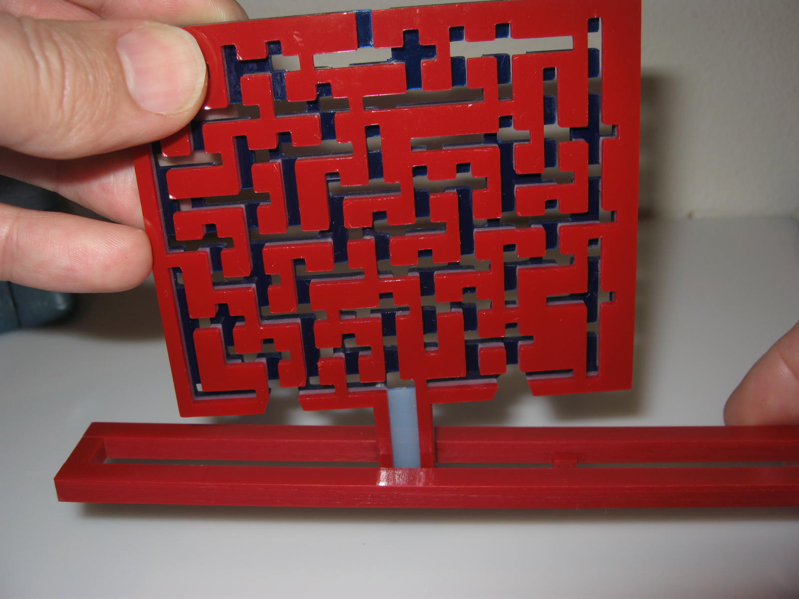
I finally managed to build my Cooksey-inspired flat maze on the SD300.  My last build failed because I'd been using a worn cutting knife, and this model packs a whole lot of cuts into a very tight space.  I put in a new, factory-calibrated knife shortly before building this model.


I'd used three colors by switching materials between the major areas of the puzzle.  That yielded a surprise bonus because unused material was consequently color-coded to easily distinguish the difficult middle section.


I had programmed SDView with an elaborate scheme of peeling cuts to ensure the middle layer could be cleared from the outside, but I'd still overlooked a design detail.  Consequently, a lot of the material had to be freed by tediously tugging pieces of material sideways before pulling it out through the openings.


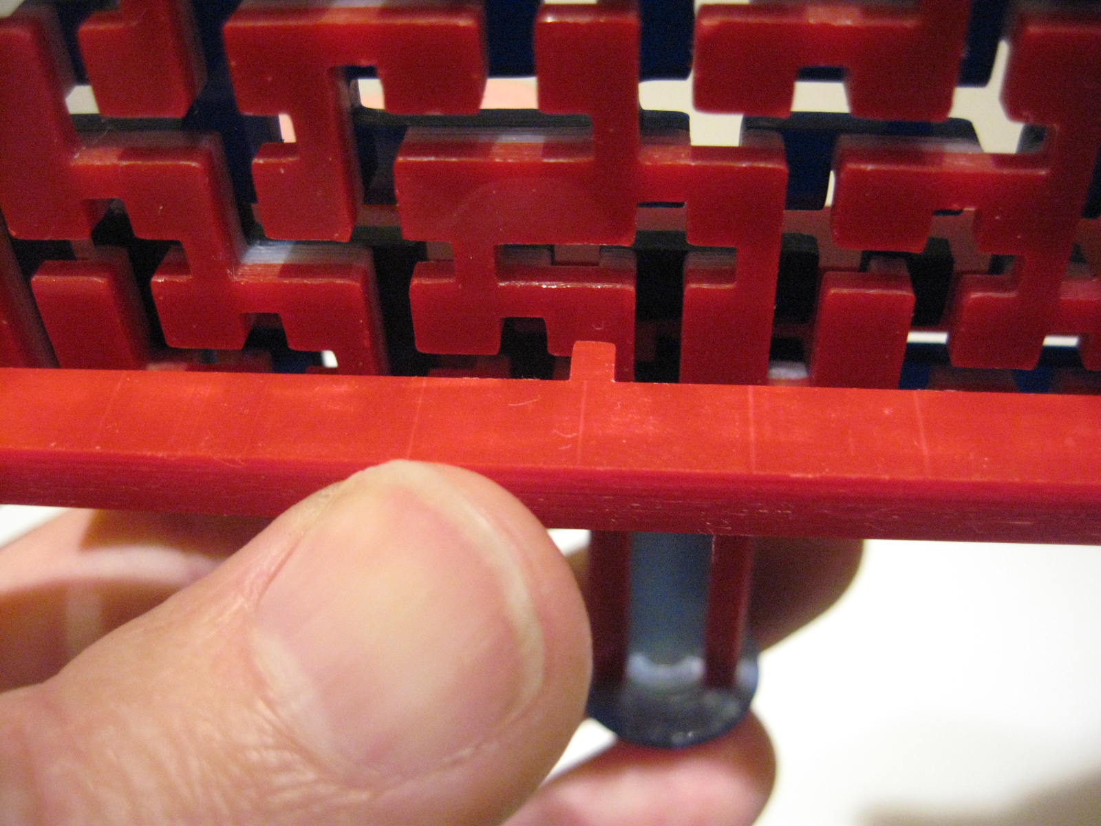
When the puzzle is fully assembled, the shuttle rests in a grooved handle.  The side walls keep it securely nested in the handle.


A disc at the bottom of the handle prevents the shuttle from coming off at the end, so the only path to remove it is to slide the shuttle into (and through) the maze.


The tab on the shuttle only allows movement along one axis (vertical) when it travels on the red side.  Horizontal  movements are blocked so long as the tab rests on the red-side grooves.


Another tab can be pushed into the blue grooves on the flip side of the maze.


Engaging the tab on the blue side disengages the tab on the red side, so horizontal movement is no longer blocked.  This allows the shuttle to move left & right as far as the groove on the blue side permits.


The user navigates the maze by alternately engaging the tab in the blue side for horizontal movements and engaging the red side for vertical movements.  Neither side exhibits the actual maze, so the correct path is not apparent.


Eventually the shuttle emerges from an opening near the start of the puzzle.


The shuttle is still hooked over the puzzle's handle, but now the tabs aren't locked into the grooves in the handle.


This arrangement allows the shuttle to spin around on the handle so the tabs move to the other side.


Now the shuttle can re-enter the maze, but with the tabs on opposite sides from before.  Now the horizontal movements occur on the red side and vertical movements on the blue side.  It's a completely different maze, without any similarities to the first.


By navigating through the mazes as shown, the user can eventually remove the shuttle through an opening at the top of the puzzle.  Naturally it's not quite as simple as it seems because there's still a subtle subterfuge or two.