Thursday, October 20, 2011

"Screwy" Screw

 A Thingiverse user saw my Wrong Way Nut video on YouTube, which showed two nuts traveling in opposite directions on the same screw thread.  He was inspired to create his own version of it, which he named Screwy Screw.  Full marks for that name!

It was interesting to see how he came up with a similar solution, yet made some vastly different aesthetic choices.  Most conspicuously, his Screwy Screw is much larger than my own bolt model.
Here's a quick video comparison of Screwy Screw against samples of Wrong Way Nut built on my SD300 and another sample built by Bradley Rigdon courtesy of http://printo3d.com/
Here's a closeup of the FDM samples of Wrong Way Nut, built by Bradley Rigdon.  Notice the funny patterns on the side walls?  See below.

Below is a closeup comparison of a nut built on the SD300 (red) and one built on a Dimension by Stratasys (blue).  Both build processes produce these wave-like patterns, often referred to as "chatter", as a result of very subtle vibrations that occur as the machine changes direction at the corners.  The marks don't affect the model's tolerances--in fact they're hard to see except by examining the model's sheen under a bright light source as here.
STL files for Wrong Way Nut are downloadable from Thingiverse here.

Sunday, October 16, 2011

Gear O'Clock

Last week Bradley Rigdon shared Gear O'Clock, a novel clock that indicates the current time using a large geared ring with numbered tabs around its rim.  This week I posted a set of Accessory Parts to adapt or customize Gear O'Clock.

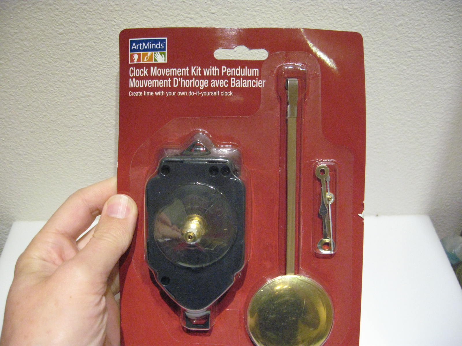
Bradley used a clock movement salvaged from an inexpensive wall clock he bought at Wal-Mart.  I set out to adapt the parts for use with an ArtMinds clock movement from my local Michaels craft store.

For the benefit of Thingiverse users, here's a detailed explanation of my accessory parts:


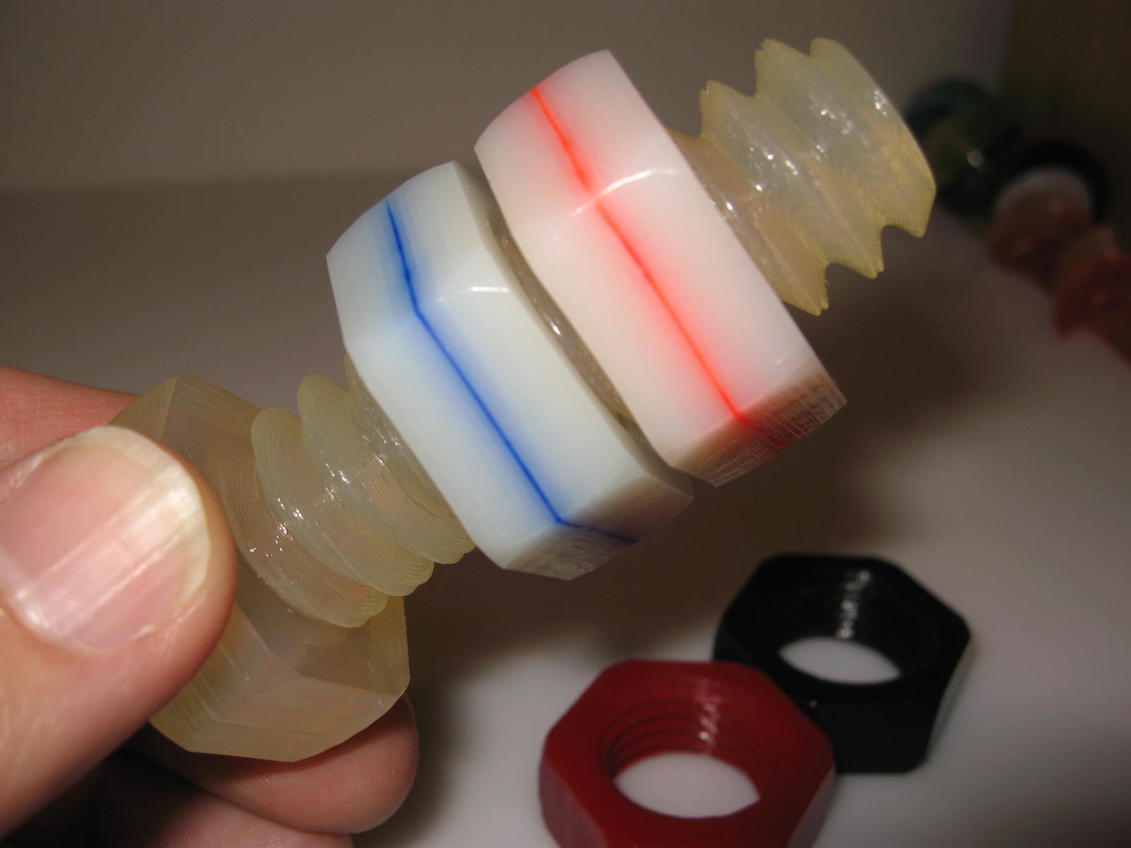
Clock Drive Gear slotted NO SUPPORT.stl has a slotted opening that fits over the threaded hour-hand shank on the craft-store clock movement.   It took some effort to avoid excessive overhangs so the part retains its buildability on hobby 3D printers.  I added a wide opening on the back side of the gear because some of the craft store movements have big shanks (like this one).


The slotted-shape of the shank keeps the Drive Gear synchronized with the shaft, just as a conventional hour hand would be.  The clock movement kit includes a threaded brass ring that screws over the Drive Gear to secure it in position.

Some of the clock movement kits have short shanks and others have really long shanks like the one illustrated here, so I added a small fence inside the deep gear teeth so the driven clock gear won't tend to walk out of the back side of the Drive Gear.

Bradley's Clock Base ring is 10 inches in diameter so it can't be built in one piece on the SD300, nor on most hobby 3D printers.

Clock Base div4.stl divides the Clock Base into four parts, which can be spliced using the number tabs at the 3, 6, 9, and 12 o'clock positions.
 The number tabs are keyed into holes in the Base Ring, so I glued one number tab to the end of each of the four parts.
 Then join each piece to the next by hooking it into the keyed holes and injecting glue between the surfaces.  Notice how the diagonal join ensures a gradual transition from one section to the next so the gear won't snag when it turns in the clock.  Be sure to attach the numbers counterclockwise relative to an ordinary clock!


My revised Drive Gear exposes a hole for the clock's second hand, so I designed Clock Seconds Gear.stl to cover the hole and add a little animation to the clock.

This gear has a hole and a slot in the back to accommodate the original second hand from the clock movement kit.  The original second had can be left intact or clipped off.

After the Clock Seconds Gear is attached to the second hand parts, it pushes into the exposed opening in the clock shank.

The craft-store clock movement has a built-in wall hook so it wouldn't fit in Bradley's enclosed Clock Mechanism Mount.  Clock Mechanism Mount cutout.stl adds a cutout to accommodate the movement's wall hook.


Some clock movement kits feature a moving pendulum, which adds even more animation to the clock.  So I built the even-larger Clock Mechanism Mount Pendulum.stl mount which has another cutout on the bottom for the pendulum mechanism.
Clock Gear Pendulum.stl is a gear-themed pendulum for use with the pendulum-type clock movement kit.


For further reference:
  • The original Gear O'Clock files are located at Thingiverse
  • My accesory files are located at Thingiverse here
  • Bradley's video shows how the clock should be assembled at YouTube
  • Here's a video showing my clocks with moving second hands and pendulum.
  • An online shop that offers all sorts of clock kits at http://www.klockit.com/

Thursday, October 13, 2011

Rhombic Dodecahedron Puzzle

I just shared a simple Rhombic Dodecahedron Puzzle at Thingiverse, consisting of four identical pieces that fit together to form a solid shape.  The concept is very similar to my previous marble puzzles and cubic trisections, but using four parts instead of just two or three.

The idea of using a shape with four-way symmetry was inspired by George Hart's Air puzzle, which is described on his web site and briefly demonstrated in a YouTube video by Roxanne Wong.

Like my previous dissection puzzles, the pieces have a distinct orientation so they only fit together if they're all pointed the same direction.  Technically that means my puzzle only one-eighth as many duplicate solutions as Air but that doesn't mean it's any harder to solve.

Here's a video that demonstrates how the puzzle works.

Tuesday, October 11, 2011

Power Interruption

Last weekend a brief blackout interrupted the SD300 while I was recording a video.  I kept recording and captured the SD300's recovery when the power came on again a minute later.  This video is embarrassingly awkward and rambling, but it's potentially interesting because most 3D printers can't recover as elegantly as the SD300 did in this video.  (More on that below.)


The SD300 is connected to a netbook running on batteries, so it recorded exactly what the SD300 was doing when the power went off.  The log says it was "Taking logical tool 4" which means it was picking up the 1mm Anti-Glue pen for masking fine details, whereupon it suddenly encountered a "WriteFile Error" because the SD300 had lost power and stopped responding.

When the power came on again, the log recorded how the computer re-established its connection with the SD300.  Because the SD300 remembered it had been building a model it calibrated the Z-axis to the top of the model instead of the top of the build table.

Recovering from a power failure isn't always so effortless as it was here, but it's usually quite manageable.
  • The computer didn't lose power.  If the computer had also lost power then it would have been necessary to reboot and start the SDView software again.  The computer saves a copy of the current model on the hard drive so it can recover and continue if the computer is turned off during a build.
  • The SD300 just happened to get interrupted between changing Anti-Glue pens.  As a safety measure the SD300 won't initialize until it detects all pens are parked in their storage holders.  If it had lost power while it was actually using a pen then it would have requested the user manually return the pen to the storage holder before it would re-initialize.
  • Additionally, if the SD300 is interrupted while the top layer of the model is still attached to the material roll then it would need to cut it free before it could initialize the Z-axis.  If that had occurred, the SD300 would have adjusted the table to a safe position, reset the XY axis, and requested permission from the user to "Trim layer?"