Thursday, December 22, 2011

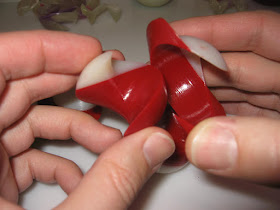
Rapid Evolution of "Candy Ball"

Over the weekend I built a simple test model that inspired me to work on a new (but familiar-looking) puzzle design that rapidly evolved in the next two days...

As an experiment I recently built a two-part shell that fits over my existing Green Marble puzzle, following exactly the same contours when the two pieces are precisely aligned.

I added a dash of green color to the model while it was being built, just to help identify the parts.  Serendipity!  The green calls attention to a swirly shape like a yīnyáng on the surface of the outer jacket.

The marble sticks out of an opening in the jacket, opposite the green yin-yang, and it can turn freely inside the jacket.  By coincidence the swirly shape can be replicated by moving the marble around but doing so causes the marble to block the whole puzzle from being disassembled.  Could I design a new puzzle that deliberately includes such a hint at a false solution?

Next I built a whole set of parts based on the same curved geometry as Green Marble with a 2-part inner ball and a 2-part outer shell.  The shell includes a round dome centered on the swirly shape, opposite an opening where the ball sticks out.  I switched between red and white material, hoping the coloring scheme might emphasize the illusion.  The colors remind me of peppermint candy.

The ball pieces fit inside the shell pieces, then the whole thing screws together.  It looked cool, but the screw action was a bit too pronounced for my taste.

 The color coding worked perfectly.  The white dome formed a ball-like shape with the same swirly shape as the green puzzle.

On the opposite side, the marble could be turned until it also exhibited a similar swirly shape.  The contrasting white color on the ball further emphasized the swirly shape, but the puzzle won't open when the swirly shape is exposed.  The camouflage works very well, but there were plenty of other details I disliked: the correct solution required too much unscrewing, the jacket pieces were too flexible, and the ball was too hard to maneuver inside the jacket.

Applying what I'd learned, I designed a whole new model from scratch without using any of the model data from Green Marble.  It looks very similar to the last model but there's less twist and the geometry is better optimized for the ball to move inside the container.

As it turns out, the newest design has an easy-to-find method of taking it apart without aligning the pieces as intended.  If the ball is turned so the white portion sticks up at the top as shown here the outer shell can be gradually withdrawn by pushing it to the left while the ball rotates and unscrews itself within the jacket.

Looking back, the previous version didn't have that problem because the red section was wider and the twists had overlapped so there wasn't as much freedom to move the jacket independently of the ball inside.

This design evolved rapidly until it reached a dead-end, so now I have an opportunity to go back a few steps and see if I can develop it into a fresh puzzle.

Tuesday, December 13, 2011

Hands free memo holder

I had intended this memo holder to use a marble to grab papers behind a wedge-shaped panel.  But the marble didn't work very well so I 3D printed a plastic cylinder that worked better.  It works by sliding papers up into the slit behind the cylinder, whereupon the force of gravity traps the paper between the cylinder and the back plate.

There are two versions, one plain and one with slots added for hanging lightweight articles.  After a little more experimentation I modified the cylinder into a barrel with a fat middle section.  That held papers better than the cylinder.  I rebuilt the memo holder with side walls oriented for better transparency to illustrate how it grips papers by the wedging action of the red barrel.


Here's video that illustrates how it works...

This particular note holder was attached to the wall using a small Command brand adhesive strip.

I also made a refrigerator-magnet version by trimming a square from a worn out magnetic pad from my SD300 and gluing it to the back of a memo holder.

STL and STP files for this model are shared here.

Saturday, December 10, 2011

Helical Burr Followup

After my Helical Burr Experiment had required sanding to make the pieces fit together, I refined the data and built a second model just to fix the problems with the first.  The new one (on the right) fits together smoothly, but it still has impractically-thin walls so it's just another experimental prototype.

I'd intended to design it so the parts could only be put together in one specific sequence, but testing the new model revealed a slight flaw: one of the pieces could be put on (or taken off) out-of-sequence because I'd only blocked movement in one of the two directions it might move.  I probably wouldn't have discovered the oversight without building these test models.

Here's a movie demonstrating how the puzzle works and revealing the design oversight.

One of the pieces had some exceptionally thin edges, which came out kind of wispy the first time so I tried building it in a horizontal orientation for comparison.  The new orientation is probably a bit stronger, but the difference isn't compelling.  Both parts work about the same.

I will probably start over from scratch because of the thin walls and un-blocked movements, but I consider it a very successful experiment nevertheless.

Tuesday, December 6, 2011

Adapting the Magic Screw for Makerbots

Last month I shared my Wrong Way Bolt model, but home users found themselves unable to build functional copies of it using hobby-type 3D printers like the Makerbot Thing-o-Matic.  The model's geometry seemed to fall within the rule-of-thumb limits, but I looked closely at individual 'slices' of the model and thought about what would actually occur when it was built using a hobby extruder.

Here's what might have happened.

At left is a slice of the trick nut, color-coded with shades of red to indicate the region to be built for the present layer.  Bright red areas are supported by the layer below while dark-red areas are unsupported overhangs.  When an hobby-type 3D printer tries to build the overhang marked with a circle its extruder would follow the path in white but the thread of extruded plastic won't have any support.  As a result, the thread will be pulled into a straight line between the two points where it's supported by the layer underneath.  The Makerbot would probably build some of the overhang, like the diagram at right.  It would probably need multiple layers before it could build that whole overhang, but each layer moves the overhang to a different place (because it's a screw) so the hobby-printer wouldn't have a chance to catch up.

The model could probably be adapted for hobby-type printers by designing the threads with a goal of eliminating the concave shapes.  Overhangs could probably be built with very high accuracy so long as they didn't have curves or corners in the unsupported regions.  So I designed a trick thread with a cross-section whose overhangs form straight lines, like so...

I don't own a Makerbot (nor any other hobby printer) so I don't really know if this will be any more buildable than the model I'd originally designed for my SD300.  But it's a starting point, in any event, as the trick threads function correctly and I'm sharing the source data so other users can adapt it if needed.

This new model and its source data are available from Thingiverse here so anyone can download it and edit it.